Your basket is currently empty!
Blog
-
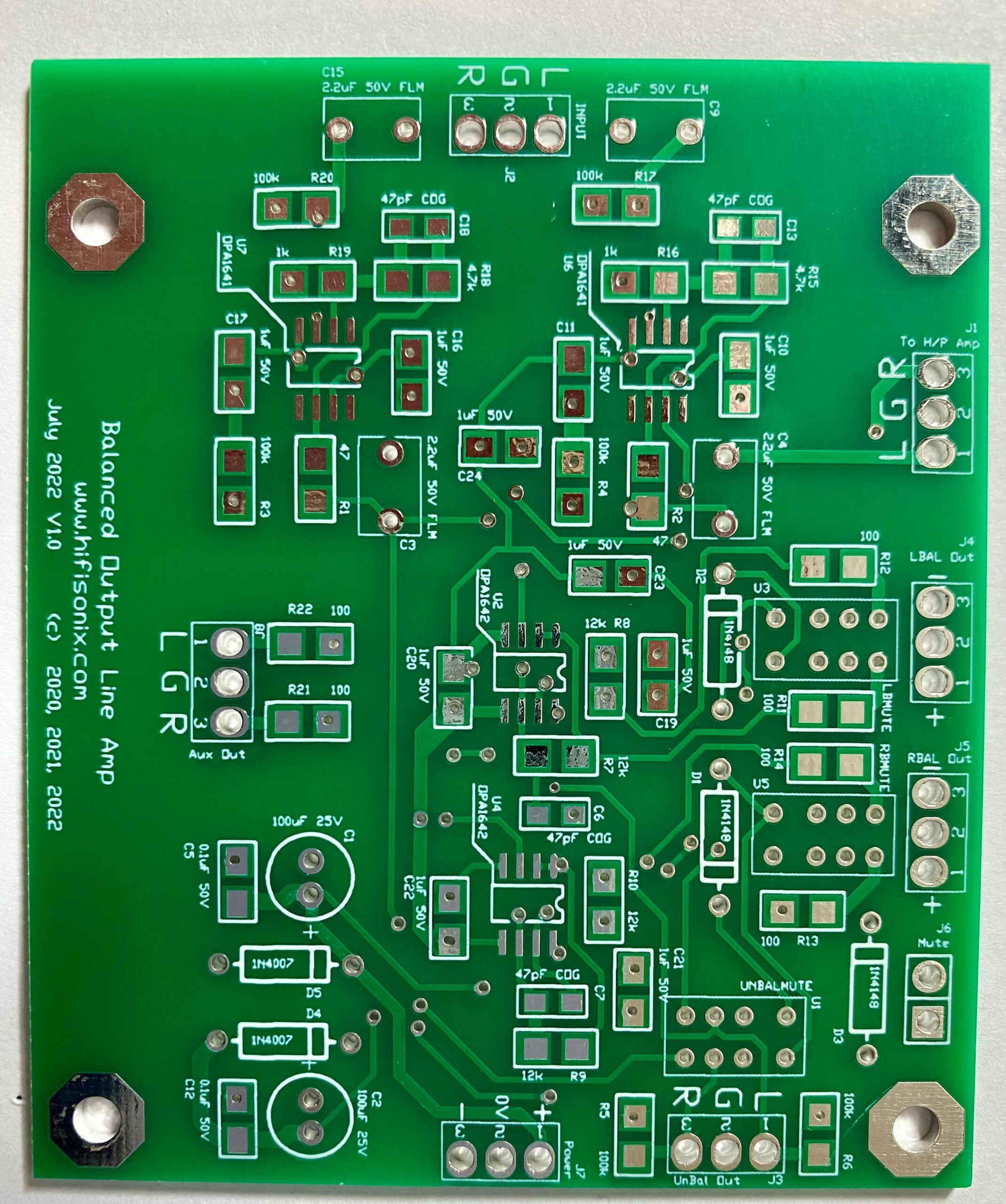
Hifisonix High Performance Balanced Line Stage
Click here to buy a stereo PCB for this line stage over in the Shop.
Click here for some measurements of the Balanced Line Stage
This compact OPA1641 and OPA1642 board is the perfect building block around which to build a high-performance line stage.
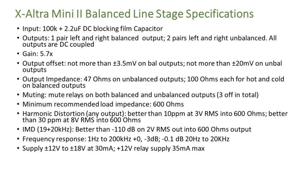
Here are the specifications for the Balanced Line Stage
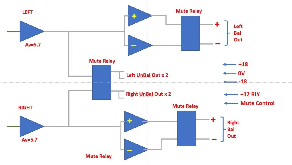
Here is a block diagram of the Balanced Line Stage
-
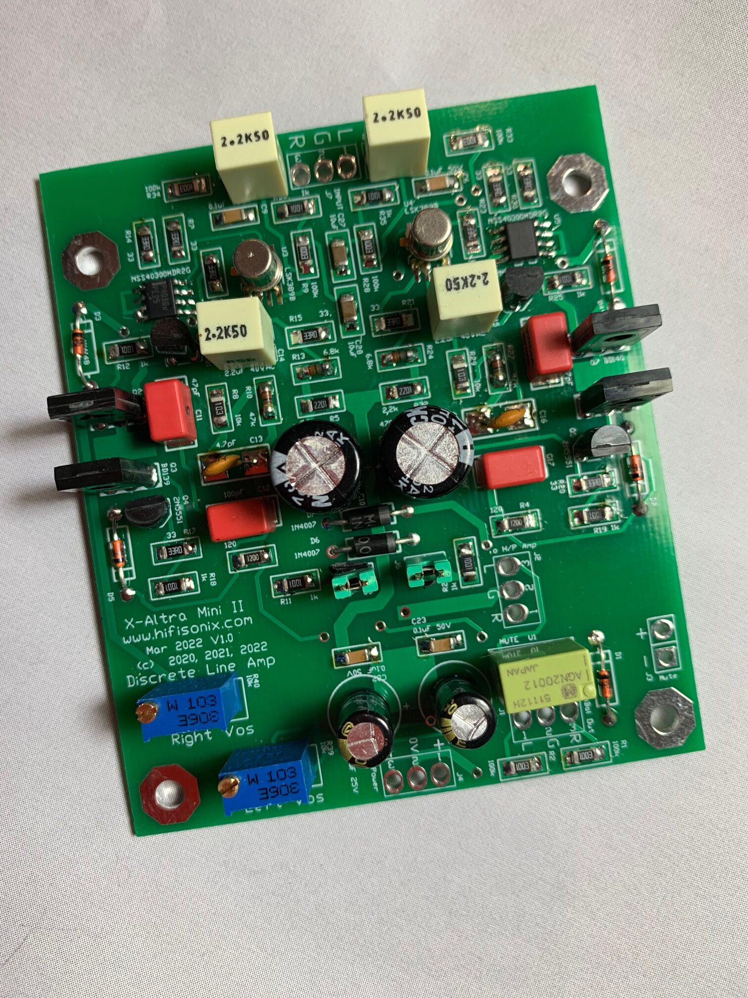
Hifisonix Discrete JFET Input Line Stage
This discrete JFET input line stage can drive a 2k ohm load to 6V RMS in class A at less than 30 ppm distortion and at 3V RMS into 2k ohms, the distortion is around 7ppm at 1 kHz. The output stage runs at 20mA standing current. A jumper allows the user to select either standard Miller Compensation, or Transitional Miller Compensation (TMC). Output mute relays can be controlled by a user provided circuit, or, they can be driven off the /MUTE output available on the Hifisonix Standard PSU.
Here are some performance measurements using the Texas Instruments JFE2140 dual JFET in place of the LSK389 originally specified. The TI device offers better device matching and slightly lower overall noise – its also readily available from Mouser
-
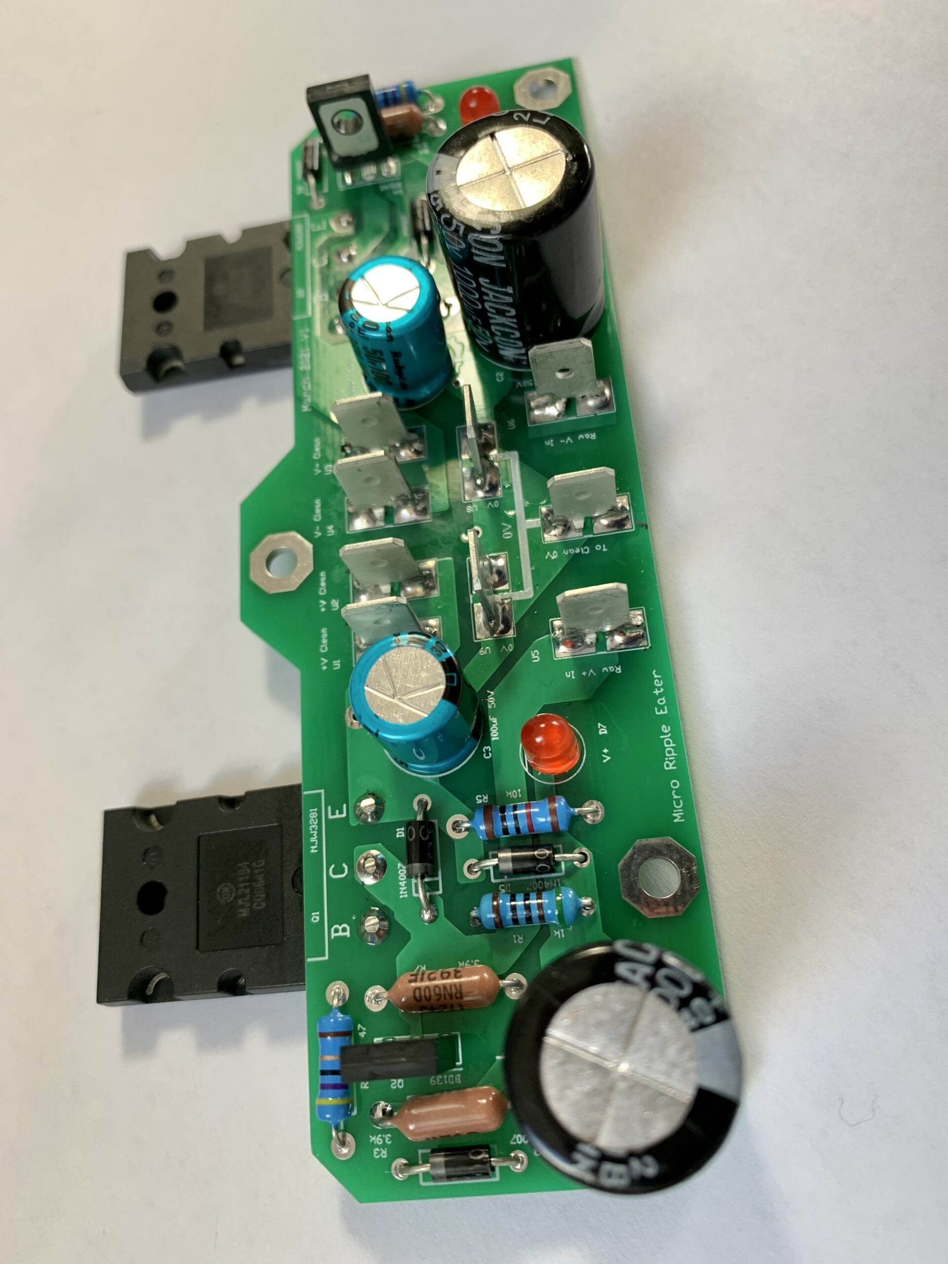
Hifisonix Micro Ripple Eater
Click here to buy a Micro Ripple Eater PCB in the Shop
This simple ripple eater (aka MRE) can deliver up to 10A per supply rail (provided it is suitably heatsinked!) and will reduce mains related ripple on amplifier supply rails by up to 40 dB and as much as 50 dB at HF.

The board is small, compact and easy to mount virtually anywhere within the amplifier chassis. You can use a single ripple eater to comfortably power stereo amplifiers of up to 100W per channel, or you can use one per channel to clean up the supply rails on higher power amplifiers. The series pass transistors are not critical and any 15A TO3-P or TO247 type packaged devices will work.
The Hifisonix MRE makes a perfect upgrade to class A amplifiers where the usually heavy load current can cause excessive supply rail ripple. At 2.5A load current, the MRE 100/120 Hz supply rail ripple is under 20mV vs 1~2V pk to pk using a standard rectifier + reservoir capacitor setup. At higher frequencies in the audio band, it is even better and with good amplifier construction and cable dressing, can be well below 10mV pk~pk. Further, the slow start-up of the MRE helps to reduce switch-on thumps from the speakers.
Download the PDF build doc below (updated 4th December 2022)
Can the MRE be used with amplifiers that have supply rails > 50V?The MRE is designed to work with amplifiers with supply rails of up to +-50V. If you want to use it with higher supply rails, the voltage rating of the capacitors has to be increased. The maximum diameter on C1 and C2 is 16mm and on C3 and C4 10mm. The transistors specified in the BOM are good for up to +-80V supply rails.
(Note: The pictures show the slightly older version of the MRE. The newer version is a bit smaller. The Hifisonix Universal Chassis drill pattern accepts the newer version of the MRE – the older layout version is no longer available)
-
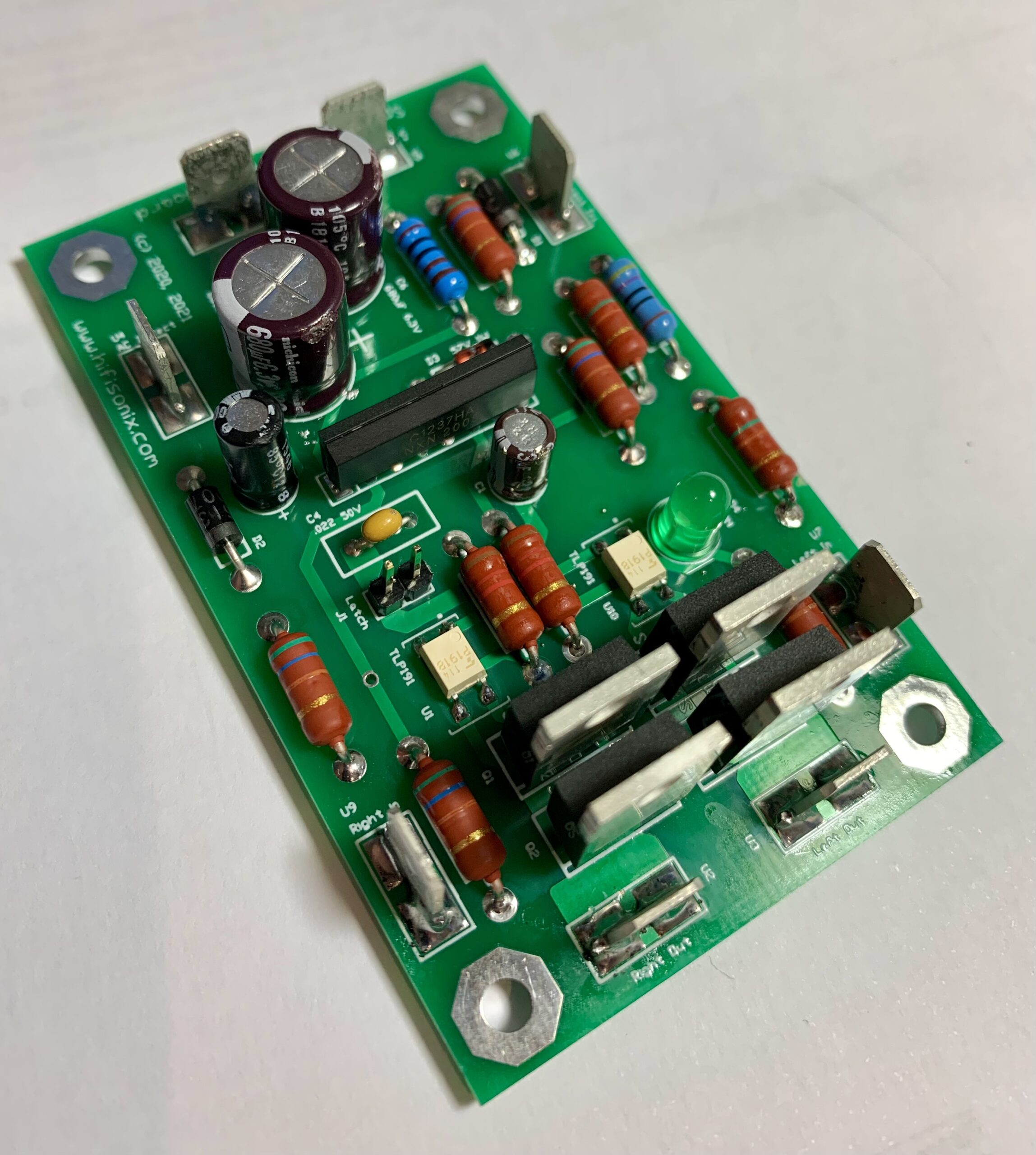
Hifisonix Speaker Protection Board
This simple, low cost speaker protection board measuring just 82mm x 50mm uses the ubiquitous UPC1237 from Unisonic, a Taiwan based semiconductor manufacturer. The circuit will work from 25V through to 75V and uses mosfets to switch the speaker load rather than relays which are problematic and unreliable. A current overload input is also provided, allowing builders to arrange to sense an amplifier output short circuit and rapidly disconnect the amplifier output. The presentation below describes the operation and how to select resistor values for different supply voltages (updated April 2023).
ATTENTION: If you are using the speaker protection board with the new nx2 amplifier, R7 must be changed to 33k. The reason for this is these amplifiers use a random phase opto-triac that switches the current protect output on the amplifiers to the +ve rail. The UPC1237 maximum current into the current trip input cannot exceed 3mA, otherwise the chip will be damaged.
Here is a short presentation on the use of mosfets for speaker switching in amplifiers
-
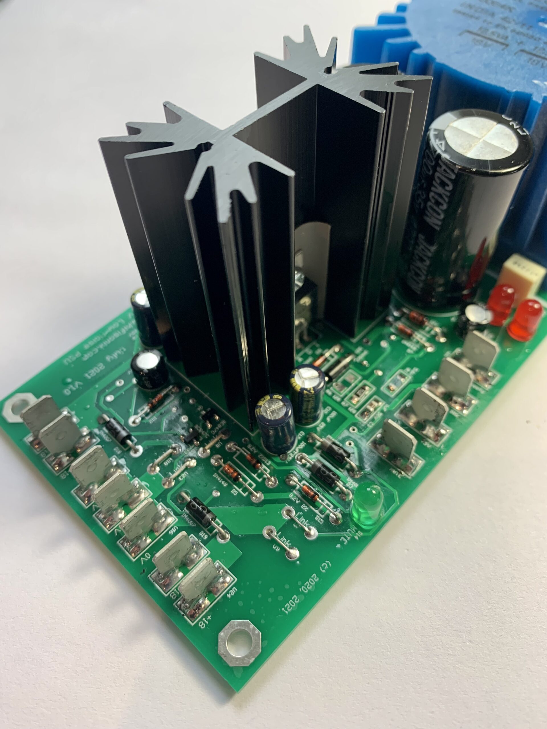
Hifisonix Standard PSU
Click here to buy a PCB for the Standard PSU
Click here for the build documentation
The Hifisonix Standard PSU features low noise, up to 400mA per rail output current, a MUTE relay driver to ensure when the load powers up or down there are no clicks or thumps, a +12V 40mA relay PSU and an auxiliary +5 or +3.3V supply (60mA max current draw) for powering any auxiliary logic or microcontroller circuits.
Output voltages are trimmed to exactly +-18 volts by means of two trimmer potentiometers. The power supply features very low full load (15 or 25W depending upon the power transformer chosen) noise with mains peaks at or below 100uV and thermal noise below -130 dBV.
-
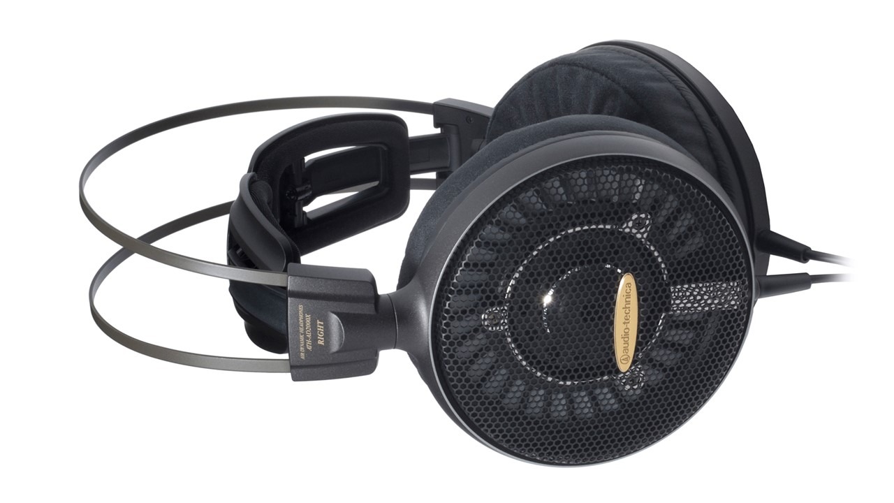
Hifisonix HPA-1 Class A Headphone Amplifier
The circuit combines a dual ultra-low distortion opamp, the LM4562 or OPA1642, with a class A discrete power output stage to deliver outstanding performance both measured, and sonically. The complete amplifier, including the opamps, runs in class A. Into 60 Ohm headphones and above, the HPA-1 remains fully in class A up to the rated 21 V pk-pk output swing (note, it will actually swing a few volts higher on higher load impedance headphones).
Click here to buy PCBs for the HPA-1 Headphone amp over in the shop
Attention: Listening to music at elevated sound pressure levels can permanently damage your hearing.
The document below discusses the design and presents the measurements (updated with latest PCB’s etc 15 May 2023):-
Hifisonix HPA-1 Headphone Amplifier Sept 2024
HPA1 May 2023 – How to Wind L1 and L2
The picture below shows how to wire the Hifisonix Standard PSU, which has a built in Mute function, to the HPA-1. This will prevent any power ON/OFF noises

-
Hifisonix Accurate Inverse RIAA Network
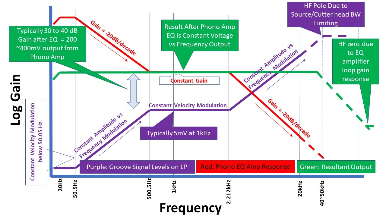
The diagram above summarizes the interaction of the cutting head response (purple) and the playback EQ (red) which produces the final flat response (green). Note that the cutting head and the phono pickup (cartridge) are velocity transducers and therefore the cartridge output rises at 20 dB/decade if the record groove is cut at constant amplitude.
Click here to buy a set of 2 Inverse RIAA PCB’s over in the shop
Designing and engineering RIAA equalizers demands a clear understanding of the signal chain requirements during the development process. Once components have been committed to a prototype PCB however, testing is required. Presented here is a simple Inverse RIAA Network, or IRN, that allows testing to be quickly and effectively done.

It is important that the RIAA equalizer response is accurate across the audio band (20 Hz to 20 kHz) and also well behaved beyond that. The usefulness of this simple tool can be gauged by the fact that, after building an RIAA EQ amp based on a design published by one of the foremost exponents of the art, testing revealed that whilst its sine wave response conformity from 20 Hz to 20 kHz was exemplary, the gain at 500 kHz was 8 dB higher that at 20 kHz, which manifest as overshoot on the square wave tests. Some simple mods to the RIAA network resolved the problem, and the response was then flat out to ~50 kHz, after which it dropped off ultimately approaching at 20 dB/decade at 200 kHz
Here is the article: Accurate Inverse RIAA
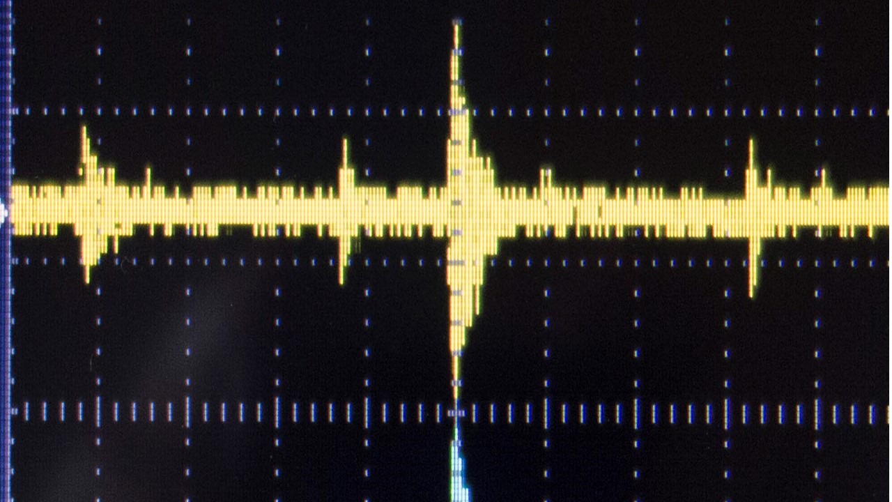
Pictured below is the conformity of a high performance phono amp using the IRN. The reading was taken with a QuantAssylum 401 measurement DAC/ADC set to 20 to 100 kHz display bandwidth sampling at 24bit/192 kHz.

Above: 20 Hz to 100 kHz frequency sweep response of RIAA amplifier fed through the IRN
Note in the picture above, the drop off in response below 100 Hz is due to the analyser response, and not the RIAA equalizer which is flat down to 20 Hz (rumble filter switched OUT).
The scope screen shots that follow (which are for the same RIAA amplifier) show how easy it is to test an RIAA EQ amp using just an IRN and a square wave stimulus. In the first picture, we see the performance at 20 Hz. The waveform tops/bottoms show a small amount of slope which is caused by a slight roll-off at 20 Hz (around 0.3 dB in this particular design).
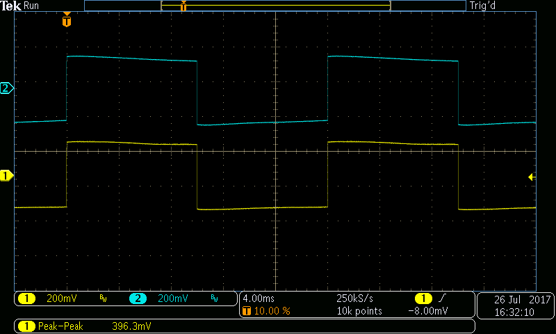
Above: RIAA EQ response to a 20 Hz square wave input stimulus fed via the IRN.
The shot below is for a 2 kHz square wave input stimulus. Since the square wave stimulus contains harmonics that are accurately amplitude related to the 2 kHz fundamental, this result implies that the response is accurate to at least 10 kHz (5th harmonic). The amplitude of the harmonics beyond 10 kHz is low, and therefore it is difficult to infer a high degree of accuracy above this frequency. Testing therefore has to take place at higher stimulus frequencies to confirm this.

Above: RIAA EQ output with a 2 kHz input stimulus fed via the IRN.
The shot below is for a 20 kHz square wave stimulus. The response is still remarkably good and in accordance with the results shown in the frequency sweep shown earlier. Since there is slight rounding of the edges, we can infer that the response has started to drop off above about 50 kHz.

Above: The response of a high conformity RIAA stage to a 20 kHz square wave input stimulus via the IRN.
Finally, the plot below shows the performance with a 50 kHz stimulus. The edges are rounded showing that the response is dropping off in a controlled manner (i.e. no overshoot or HF response anomalies) in accordance with the design requirements.

Above: RIAA EQ amp with 50 kHz square wave input stimulus fed via the IRN.
-
Using the QuantAsylum QA401 for accurate Audio Measurements
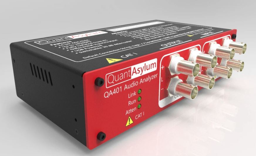
The QA 401 from QuantAsylum (superseded by the QA403) has emerged as a popular, comprehensive audio test instrument in the DIY audio fraternity and the go to instrument in many cases for commercial production testing. It combines a first rate DAC and ADC with a simple user friendly PC interface to realize a fully integrated measurement and characterization system.

In a good set-up, line level distortion measurements of under 3ppm (1 kHz) are readily achievable while the instrument’s noise floor is close to -155 dBV, allowing accurate noise characterization in things like phono and microphone amplifiers. Combine this with a host of built in test scripts and its easy to see why this $450 instrument was such a hit.
However, to get the best results from the QA 401 and it’s more recent upgraded siblings the QA402 and QA403, the user must spend some effort on the measurement set up. I’ve seen many test plots with excessive mains noise, thermal noise or subpar distortion results that have nothing to do with the QA401’s performance, and everything to do with the measurement set-up.
The short presentation below explains how noise arises in a typical measurement set-up, and then shows the reader how to set their measurement system up to exploit the full capability of the QA 401.
-
Building Quiet Audio Power Amplifiers Requires Best Wiring and Layout Practices

There is a misconception that noise pickup is reduced by placing the input RCA connectors (and similarly XLR input connectors in a fully balanced system) on opposite sides of the amplifier rear panel and then running short wires to the amplifier modules. This arrangement is the worst of all worlds. The internal loop areas available for the power transformer’s magnetic field with which to interact with are huge, even in transformers fitted with a GOSS band. Secondly, to reduce common mode RFI pickup, good practice dictates that the incoming interconnect screen be tied right at the input connectors directly to the chassis through a 10-50nF ceramic capacitor. At RF, this makes the source, the interconnect shield and the receiving power amplifier a single enclosure and offers good protection from external radio frequency interference. However, if there are any HF noise sources inside the amplifier – like an SMPSU or, more commonly, diode turn-off ringing, the internal HF loop area between the source and separated input connectors is very large, leading to noise pickup. By keeping the input connectors co-located with the signal returns bonded together and using a single RFI cap to the chassis right at the input, the loop area for HF pickup is greatly reduced.
These two slides show how to considerably reduce the internal loop area wiring in an audio power amplifier to better achieve low noise.
-
So Just How Quiet is Your Phono Stage?
You may be in for a surprise: actually not that quiet! The reason of course is that the cartridge inductance and resistance dominate the noise in any decent phono amp. To get the best in terms of noise performance, you really need to keep the input referred noise voltage and noise current to a minimum.

The spread sheet below rests very heavily on one pulled together by Stuart Yaniger (there’s a link to his original in the spread sheet) which in turn is based on the National Semiconductor ‘AN104 Noise Spec’s Confusing?’ available here
I’ve added the facility to enter the noise voltage and noise current for up to 5 opamps (or discrete input amplifiers). The spread sheet then calculates the total noise, taking into account the cartridge and amplifier parameters along with the RIAA gain which of course changes with frequency. What quickly becomes apparent is that even with a phono amplifier with say -90 dB noise floor reference 3 mV, you will not get better than -73 or -74 dB once you connect a typical phono cartridge ref 5mV input, and only with exceptional designs that carefully address the noise mechanisms at play in an MM phono amplifier, can anything approaching the theoretical maximum of 77 dB be realised (all figures unweighted and for non-resistor cooled designs).
ONLY ENTER DATA IN THE GREEN SHADED CELLS AND NOWHERE ELSE!

