This gallery features some of the work done by the Hifisonix DIY audio builders’ community. If you have any pictures of your build, feel free to send them to me, and I’ll post them up here. The gallery covers power amplifiers, preamps, line stages, and phono amplifiers.
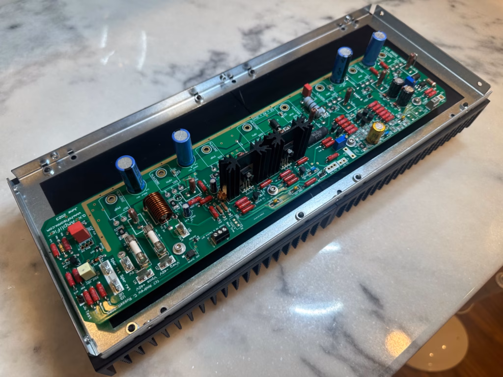
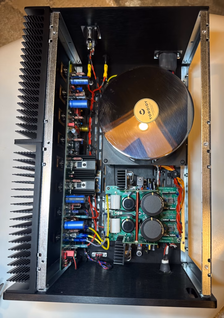
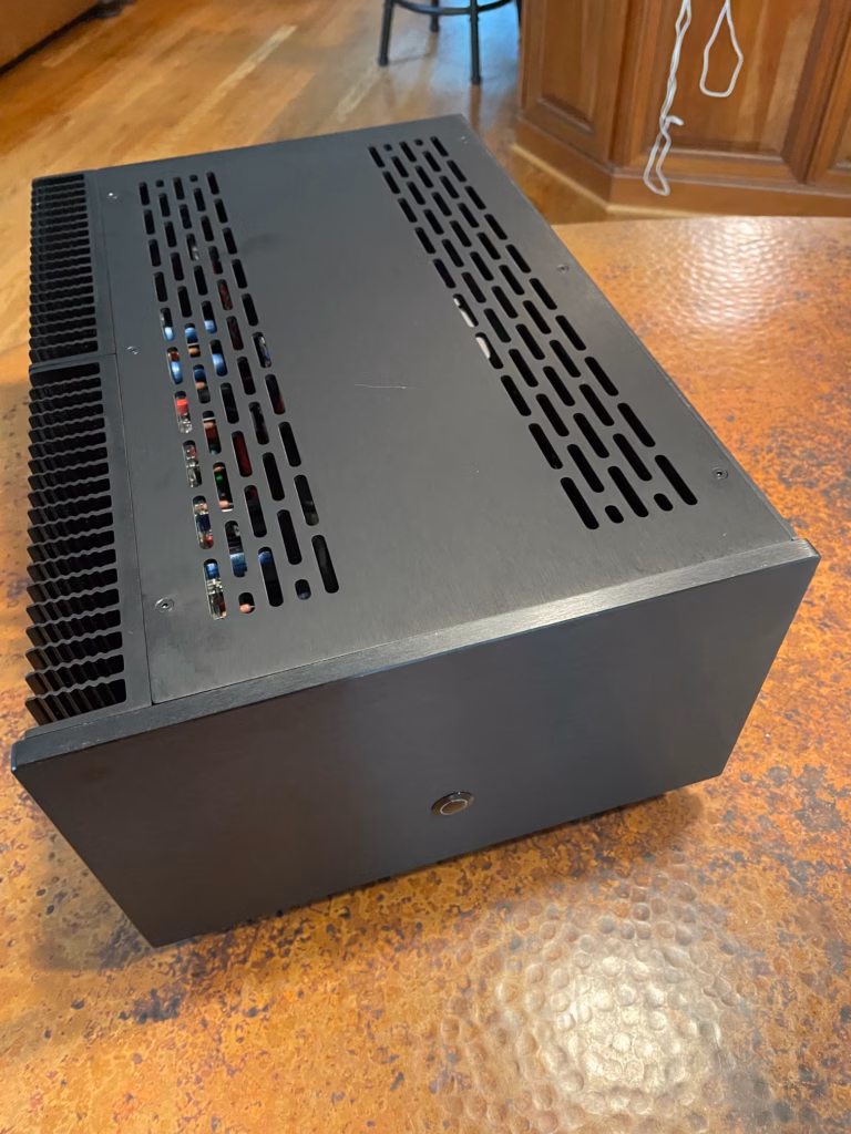
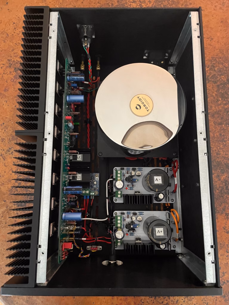
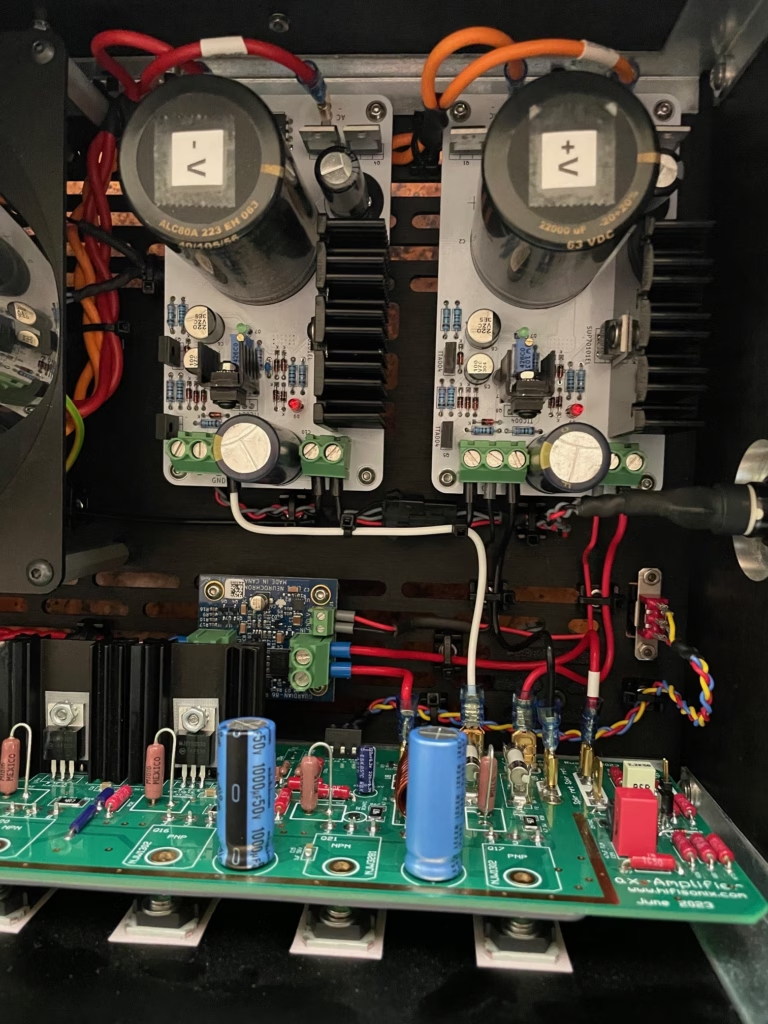
Anand Raman, who hails from North Carolina in the US, built a pair of ax-Amplifier mono blocks along with fellow builder Steven Edwards, who lives nearby. Anand, like Steven, spared no expense, and the result below showcases his stunning build. Since the 4U monoblock chassis’ were slightly smaller than the 5U version, both Anand and Steven tuned the bias current down slightly to ensure the heatsink temperature on sustained use did not exceed the recommended upper limit of 65°C. Anand used a Torroidy transformer, and protection and PSU boards from other DIY vendors on diyAudio.com.
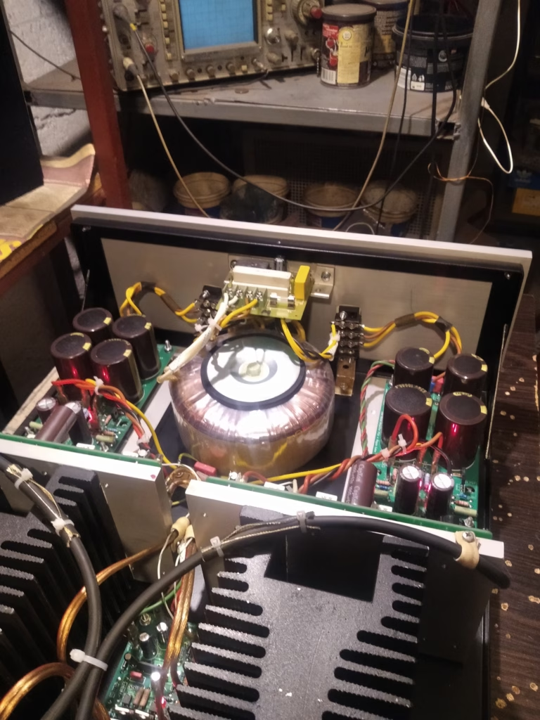
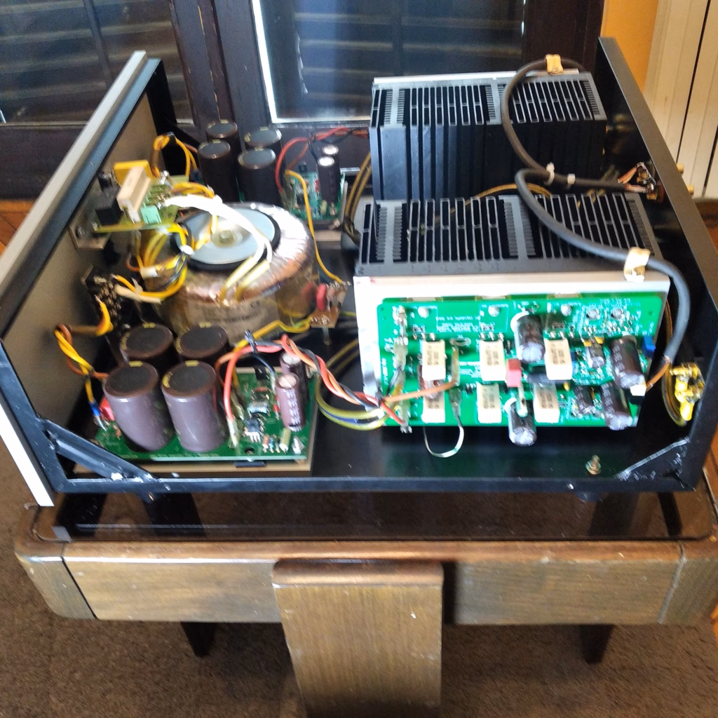
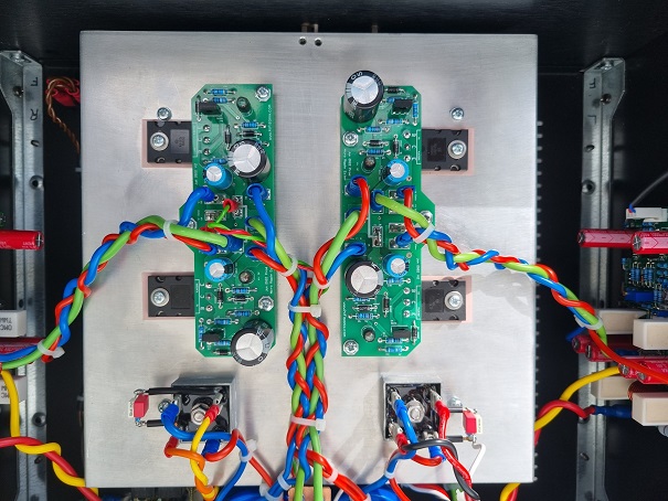
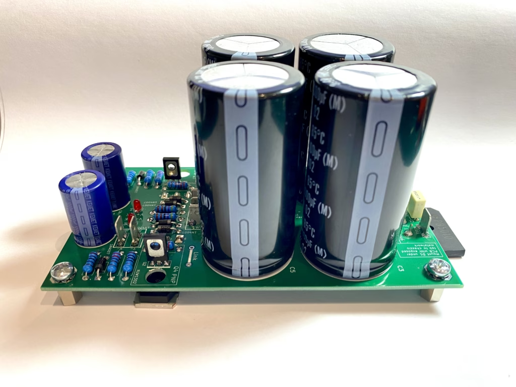
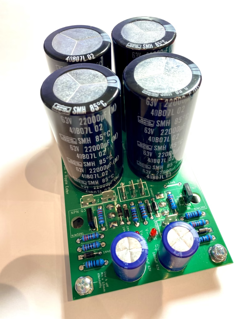
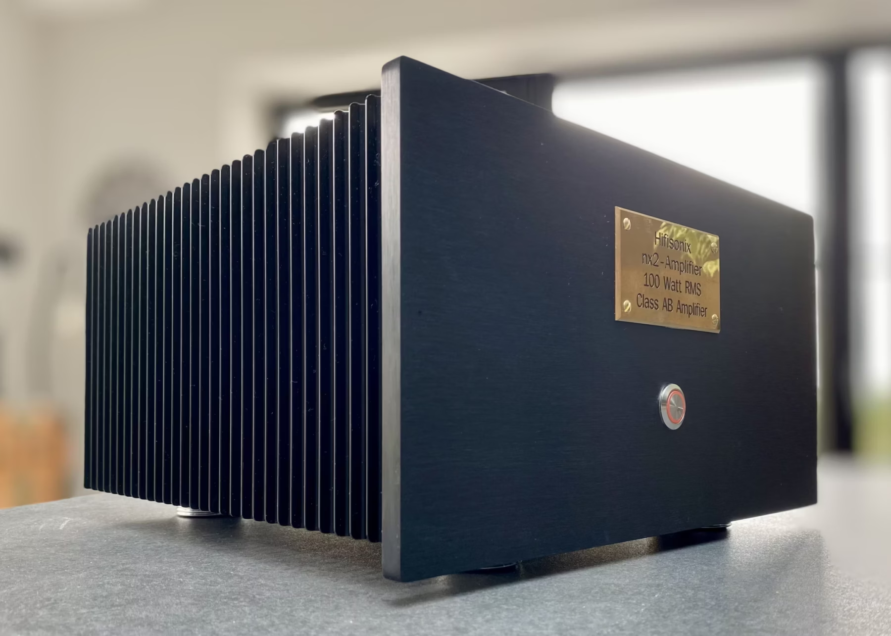
Below is Dule’s fantastic nx2-Amplifier build. Dule hails from Serbia, and used the new Hifisonix REP (aka ‘ripple Eater Power Supply) for each channel. All the necessary cabling is tightly twisted, and he and his system-listening buddies are very impressed with the sound. (See the nx2-Amplifier project page for a review of this amplifier and Vojin’s build).
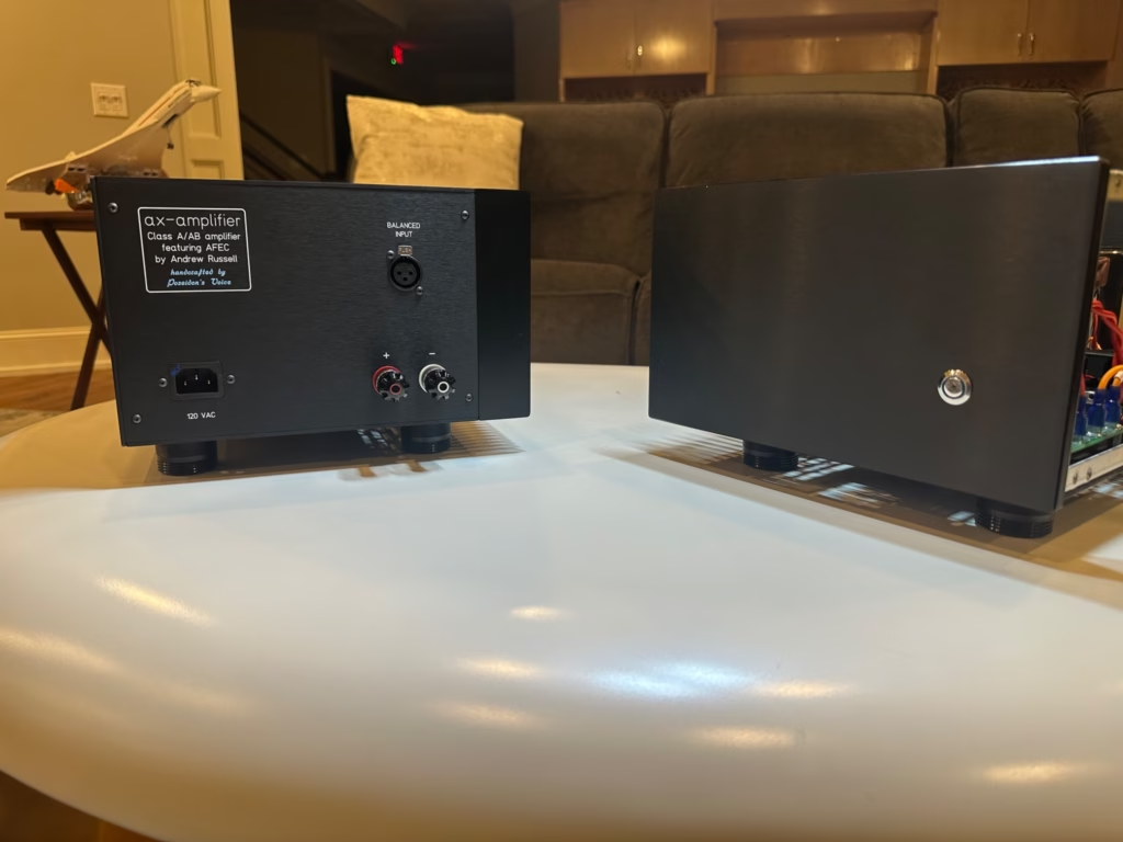
Here are some pictures of US-based builder Steven Edwards beautiful ax-Amplifier build. He elected to go with mono blocks and used the mono block housing from Modushop. Steven used a Torroidy power transformer and PSU and protection boards from other DIY suppliers on diyAudio.com.
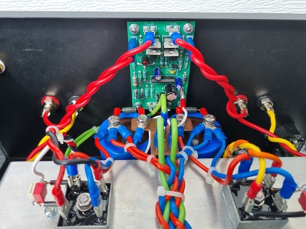
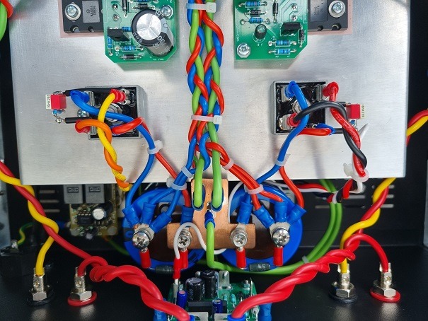
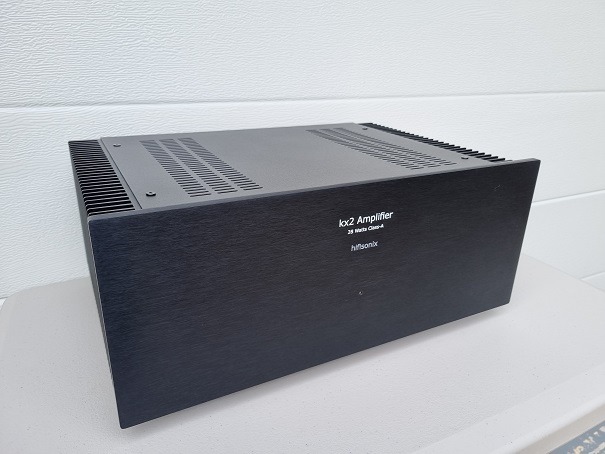
Here are some images of UK builder David Kenyon’s immaculate kx2-Amplifier build. David used a Modushop Mini Dissipante housing and Micro Ripple Eaters for each channel. David reports that the amplifier is dead quiet with his ear in the speaker cone, and that’s down to his good wiring practice of twisting the PSU cables tightly and cable tying them to ensure radiated noise is kept to a minimum.
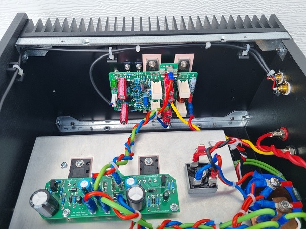
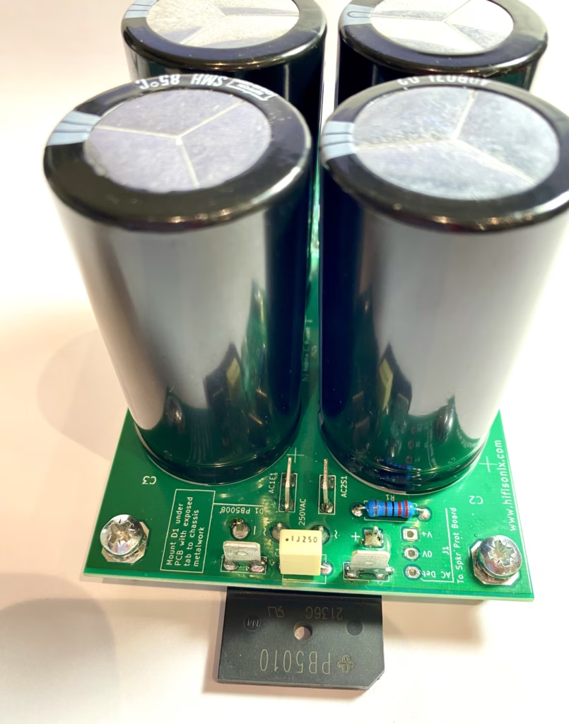
This is the new hifisonix Ripple Eater PSU aka ‘REP’. It’s designed for use with stereo class A amplifiers up to 30W RMS per channel, or stereo class AB amplifiers up to 100W per channel.
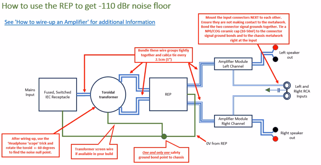
This is how the REP must be used to achieve the peak -110dBr noise floor. Note carefully the following: –
There is only one point on the chassis where the incoming safety ground from the IEC mains receptacle and PSU secondary side 0V connect – there are no other connections to the chassis.
The speaker output return cable goes back to the amplifier module 0V and NOT directly back to the PSU 0V. Why? This ensures the smallest loop area for noise generation and pickup and results in dramatically lower noise floor.
The cables to from the REP to each amplifier modules are tightly bundled and cable tied every 2.5cm (1″)
The cables from the toroid to the REP are twisted tightly and cable tied
The mains connection from the IEC connector and any power switch are twisted tightly and cable tied
Use screened cable to make the connection from the input receptacles to the amplifier module as this guarantees the smallest loop area and therefore minimises noise pick-up.
If you are getting your transformer custom wound, include an interwinding screen and a GOSS band. A GOSS band can lower radiated noise from the transformer by 6-10dB inside an amplifier chassis.
By rotating the transformer through +-60 degrees, a null point can be found that will reduce noise by a further 6-10 dB.
Always mount the input connectors side by side and make sure they are insulated from the chassis metalwork. Bond the two signal grounds together and then tie the bonded signal grounds to the chassis with a 10-50 nF NP0/COG ceramic cap right next to the connectors. This makes the input [metal] source, the interconnecting cable screen and the amplifier metal chassis a single enclose as far as RF is concerned, reducing RFI interference.
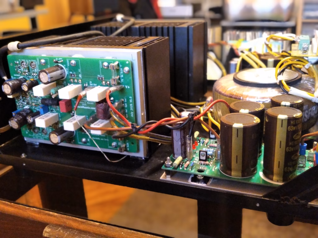
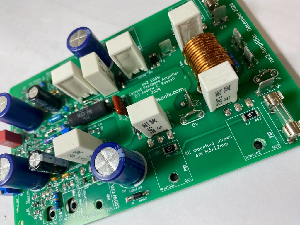
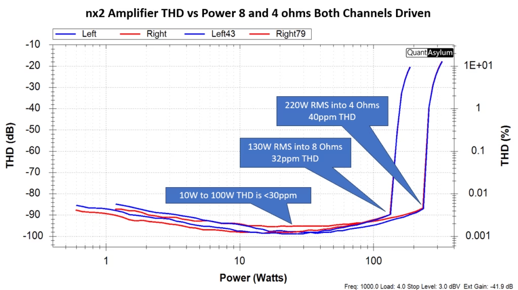
The nx2 produces >100W into 8 ohms and >200W into 4 Ohms both channels driven. At 100W into 8 ohms, the measured distortion is below 30ppm while at 200W, it is below 40ppm. The amplifier features 700ns rise/fall times and an EF2 output stage using three pairs of output devices, allowing it to drive difficult loads. It uses SMD devices for much of the small signal part of the amplifier, which ensures it is future proof, given that many TO-92 devices are no longer readily available.
I used a Modushop Mini Dissipante chassis (Part# 1MNPDA04/33/300N) for my build. Gianluca at Modushop can drill and mill the heatsinks and rear panel to the Hifisonix Universal Chassis spec. Just send him the linked to zip file when you order your chassis. Note, the Hifisonix Universal Chassis drill spec will also cater for the sx, kx2 and original nx amplifiers.
If you have any questions, let me know, and thanks for visiting hifisonix.com. As always, I am here to help with any technical issues.
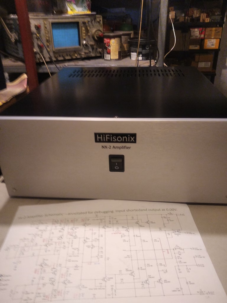
nx2-Amplifier: Some Background
In 2012, shortly after I published the sx-Amplifier, a very simple pared-down class A CFA, I tweaked the design to come up with the nx-Amplifier that delivered 100 Watts RMS into an 8 Ohm load and simulated at 0.007% distortion at 80 Watts RMS. Like the sx-Amp it was based on, the idea was to keep the amplifier simple, and easy to build but still have good overall results and sound. The transimpedance stage (aka VAS) was a simple single transistor implementation preceded by a standard CFA diamond buffer input stage, while the OPS was an EF2. Two iterations of the nx-Amp board were made – the initial release in 2012 and then a further small update in 2016. About 150 sets of each release were sold through Jim’s Audio and from what I can tell, most of those were built.
Accompanying the amplifier boards was a rather complex and unwieldy power supply and protection board that I called the ‘PSU +Prot’ that offered +-50V DC rails, DC offset and overload current protection, and power ON/OFF speaker muting. The Zobel network for the amplifier modules was, unusually and not very cleverly, incorporated onto the PSU +Prot Board. I received lots of excellent feedback about the sound which builders loved. However, in retrospect, I think some aspects of the design were idiosyncratic as described in the presentation.
Fast forward 13 years to 2025, I’ve learned a lot, had much feedback, and so it is time for an upgrade . . . this can be approached in two ways: start with a blank sheet of paper and a brand-new design or start with what is a good basic amplifier and improve it, ending up with something altogether better than the original. I decided on the latter course of action, adhering to the ‘if it ain’t broke, don’t fix it, just upgrade it’ dictum.
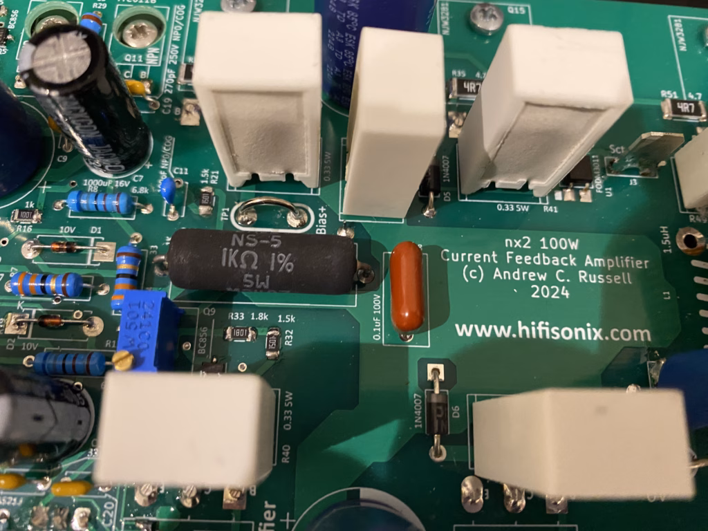
A close up of the nx2-Amplifier module (this was an earlier prototype)Another view of the amplifier module/
How does it sound? Big punchy bass with a lush, detailed midrange and what I’d describe as a delicate, open top end. I use my nx2 with my B&W 703s to listen to jazz and classical music, but it also pairs fantastically with the KEF LS50s that feature even better coherence in the top two octaves of the audio band. Outstanding imaging is an absolute requirement for me, and the nx2 complements good recordings in this aspect wonderfully in my view, where a lesser amp might fail by closing in the sound stage. The bottom end is particularly good, and I put that down to the triple EF2 output stage and the increased loop gain (about 12 dB), allowing it to deliver high LF currents accurately. I have written elsewhere about the fact that current feedback amplifiers cannot slew rate limit, and this is evidenced, in amongst other things, with exceptionally low IMD (19+20kHz) at full power, which is responsible for the very delicate, open top end on this amplifier – a characteristic the 15W RMS output class A kx2 also shares by the way.
You could argue that, as the designer and builder of the nx2, my vision is clouded by my attachment to the nx2 and the CFA topology. You of course are entitled to make that observation. However, I have heard a lot of outstanding amplifiers (and some not so good ones) over the last 50 years or so, and my contention is the nx2 is an outstanding amplifier that I would quite happily put up against any other. The nx2 incorporates all of the latest thinking in linear power amplifier design with regard to PCB layout and compensation, and coupled with modern, high-performance semiconductors, means legacy amplifiers of similar power ratings aren’t much of a match for it. If you want to enjoy is at its full potential as a high-end amp, be sure to marry it to a good power supply – don’t skimp on this and also make sure it has adequate heatsinking.
Vojin and his friend Dule, both from Serbia, each built nx2-Amplifiers recently. Vojin built one of the original nx- Amplifiers a few years ago, a precursor design dating back to 2012, and was very pleased with the sound of the original. However, both he and Dule found the nx2-Amp (which Vojin calls the ‘Temptation’) a big step up. Here’s Vojin’s review and some words about his system as well:
Let’s begin by quoting the old report: The other night we gathered at Dule’s place for premiere of his nx2. His system is: an old CD player with surprisingly good sound, Technics SL15 turntable with excellent arm and cartridge, DIY tube line preamp based on E80CC, Lundahl trafos on the output, DIY tube phono/RIAA stage, DIY two way speakers with French Triangle drivers in D’Appolito fashion. His power amps were kx2 (sold) and a big Perreaux with curved facia. Now it is time for nx2.
His build is, as usual, impeccable. Looks impressive, restrained, very nice. If you don’t have the pics, or if they are bad quality, I can tell Dule to make new photos. It gets hot, though with his specific heatsinks, but we don’t worry about that.
And the sound? I can say, and the other audiophile guest agreed, that this is the best sounding system I heard in Dule’s place. With Perreaux it was bland in comparison; now the sound is alive and involving. Bass is articulated and precise, mids are realistic, highs sparkling. Dynamics excellent. Space rendering we couldn’t check properly. No listening fatigue. We enjoyed the whole evening. The only objection I may have would be that the performance reminds me of my ‘old’ nx. Wait for AB test once I finish my bulid, hopefully in a few weeks. As I am writing this I am listening to The Shadows, pure joy End of quote.
The above was written on 17-11-25. Now, 26-12, let’s move to my own Temptation. Also refer to my ‘new vs old’ message of 17-12. To answer your queistion: I run bias at 37-38mV at test points. That is approx ¾ of what you prescribe. My poor man’s flat cooling plates can not stand full 50mV, everything gets uncomfortably hot. Considering that measured avg. SPL in my room is usually less than 80dB at 2.5m distance and my Avalons are some 86dB/W/m with 4R imped. I reckon I am in class A most of the time. As for the input caps (C1) I tried to bypass, couldn’t regulate offset, connected them back. (I think I reported this previously). Now, the Temptation is run in. I rarely turn it off, gets nicely warm, some 45Cels. I brought the aforementioned Dule’s E80CC preamp and I changed preamp-to-amp interconnect to expensive Kubala Sosna. Must say, this cable brought audible improvements. Now the best preamp to my ears is Rowland and the whole combo is singing. I would say that the Ovation (the old nx) is reticent in comparison, and still there is a lot of family resemblance. I am very satisfied with the sound of my system now. You know that feeling when you find new details on familiar recordings. And dynamics is very good, yet I can listen for hours without fatigue. Have to find money for the expensive cabling, though. And a bit of history: since I made Ovation I tried many power amps, here is what I remember:
VTL 85, good Sugden Masterclass, very good but a hint of euphony Sugden A21 integr. (forgot the iteration), similar to Masterclass An old Restek, fond memory, strong yet gentle Bedini 25/25, nice but too euphonicHiraga Le Monstre factory made (very rare), not really Hiraga Le Monstre DIY, sloppy build but pleasant sound, not for the Avalons, though
Addition 01.01.26: I played with various interconnects, got what I wanted, I can now say that Temptation is one hell of the amp. Coupled with equally good ancillary devices it can bring listening satisfaction to most listeners, with the exception of SET brotherhood, who will find it brutally revealing and too dynamic, perhaps. Compared to old nx it offers more bass, more dynamics and more details. Good work, Russell, carry on!
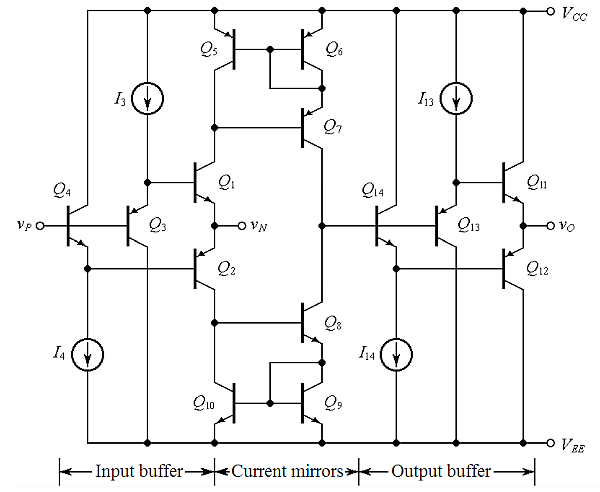
A considerable amount has been written about voltage feedback amplifiers (VFA) over the years, but comparatively little attention has been paid to current feedback (CFA) types. Both Robert Cordell and Douglas Self focus almost exclusively on VFAs, with little to no in-depth analysis or consideration of CFAs as viable alternatives to the prevailing VFA-dominated linear amplifier design orthodoxy. I have written extensively about the contortions audio designers went through in the 1960s through to the very early 1990s, as they tried to unravel the vagaries of Lin topology VFAs, to finally arrive at design methodologies that delivered low distortion, adequate slew rates and power bandwidths, while avoiding those worst of all distortions: slewing induced distortion (aka ‘SID’) and transient intermodulation distortion (TIM), or just plain good old-fashioned slew-rate limiting.
It wasn’t until Douglas Self published his first power amplifier design book (known colloquially amongst the audio design fraternity as the ‘APADH’) in the mid-1990s, and the concept of a Lin-topology ‘blameless’ amplifier, that all the key elements required to design and build an excellent VFA were documented and presented logically in a single text – but a well-implemented ‘blameless’ topology amplifier still requires sticking plaster fixes to address its irredeemable flaws. That is not to say others hadn’t taken care of the fundamentals prior to that, but the APADH was the first to put everything an audio designer needed in one document. For example, Robert Cordell produced a very low-distortion VFA in the mid-1980s that also demonstrated a clear understanding of the trade-offs required for good VFA design and addressed crossover distortion employing Hawksford’s novel feedforward scheme in the MOSFET output stage. Additionally, some ten years earlier, James Solomon’s 1974 ISSCC paper also unravelled the power bandwidth versus slew rate and front-end gm conundrum. However, some people just got it plain wrong, and Matti Otala’s claim, best summarised as ‘[high] feedback causes slewing distortion’, led a large contingent of the audio amplifier design community down a path to zero global feedback amplifiers, which are suboptimal in every respect. The real cause of the problem was of course a failure to understand the interlocking mechanisms that define slew rate, loop bandwidth, the required phase and gain margins and how distortion has to be traded off in some cases to ensure stability with any practical load.
However, in retrospect, it is clear with the VFA, the industry was dealing with a fundamentally flawed audio power amplifier topology. Really good solid-state power amplifiers only became readily available in the mid-1990s – in other words, it took a very long time from the late 1960s to the mid 1990s for the industry as a whole to fully understand what they were dealing with. In 2025 it is very much easier to design a near-perfect VFA with ample loop gain, very low distortion, and zero chance of slew-induced distortion within the audio band, regardless of the input source; the methodology and design rules have been thoroughly developed and deployed for at least 30 years.
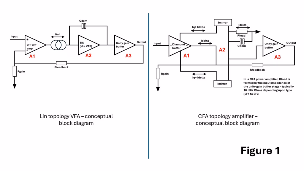
The basic topological configurations of the two amplifier types are depicted in Figure 1 below. On the left is the VFA where the tail current, Itail, which is usually set using a current source of between 2-10mA on modern amplifiers, is ‘steered’ into or out of the A2 integrating stage formed by the TIS around which Cdom (the integrator capacitor) is wrapped. With a sine wave stimulus, the maximum rate of voltage change occurs at the zero-crossing point and the maximum rate of change at any frequency given by (dVout/dt)max=2.π.f.Vp. This can be restated as the minimum required slew rate to reproduce a signal at any required voltage and frequency, so for full power, the required amplifier slew rate (SR) is SR≥2.π.f.Vp, or rearranging, fmax=2.π.Vp.SR. The onset of slewing in a blameless Lin topology amplifier is set by the front-end LTP gm and the tail current, so SR = (2.Pi.Fugf.Itail)/gm where Fugf is the open loop unity gain frequency and the gm is set by gm=Ic.q/kB.T where q is the charge on an electron, B is Boltzmann’s constant, and T is absolute temperature in kelvin. So from this we can conclude that in a VFA, the LTP gm and the tail current, along with the value of Cdom, ultimately set the undistorted power bandwidth. Push the amplifier beyond this point, and the output will start to show signs of slewing. It is important to note here that the slew rate and unity gain open loop frequency are set independently – a high slew rate does not necessarily imply a high unity gain open loop frequency, and vice-a-versa.
The right-hand side depicts a conceptual model of a CFA. Most of the signal current required to ensure that the inverting input voltage = the non-inverting input voltage flows through Rfeedback and Rgain, with only a small signal related displacement current, Idelta, being added/subtracted to this feedback current flowing in and out of the inverting input. It is this displacement current flowing in and out of the inverting input that gives this type of amplifier its name: current feedback amplifier. We can write this as Idelta = Vinv/Rgain-[Vo-Vinv/Rfeedback]. This displacement current is mirrored by the transadmittance stage (TAS) around A2 and so flows in and out of Rload. Rload is typically just the input impedance of the buffer stage, A3, and in an EF3 power amplifier for example, can confer very high loop gains in power CFAs at LF. The open loop unity gain frequency in a CFA is simply Fugf = 2.Pi.Rfeedback.Cdom. In the diagram, Cdom is shown as going straight to ground, and representative of the total capacitance at the TAS output node which will include the input capacitance to the buffer stage A3, and any other compensation and stray capacitances. You can see from the equation that Fugf can be set with just Rfeedback and/or Cdom – it does not involve the front-end gm in any way. In monolithic IC CFA’s, Cdom is internal to the device (and usually only a few single digit pF), and compensation is set only with the value of Rfeedback. In practical audio power CFAs, the current mirrors are replaced with a symmetrical TIS (aka VAS) stage, generally further raising the open loop gain substantially and Cdom is applied around the TIS in the conventional manner. Idelta peak is usually one to two orders of magnitude lower than the current flowing through the Rfeedback and Rgain setting resistors, and it can charge/discharge Cdom very rapidly. It is for this reason that CFAs do not slew rate limit and offer wide bandwidths and fast rise fall times as a matter of course. On very fast rising signal edges, the peak current into Cdom can be 4 to 8 times the Idelta standing current, in direct contrast to a VFA where the maximum can never be more than the tail current, and it is this current on demand feature that prevents them from slew rate limiting.
To summarise: In a VFA, the current into the integrator stage is set by the front-end gm and the tail current. This ultimately sets the open loop unity gain frequency and the slew rate (note these two can be set independently). The peak Itail current into the VFA integrator is always limited by the LTP tail current which is 2x the standing current of each half of the LTP. In a CFA, the peak Idelta displacement current is set by the value of Rfeedback and there is no hard stop as there is in a VFA.
What if instead of a Lin topology VFA, designers had first hit upon the CFA topology? What would the amplifier design landscape look like today, and how long would it have taken to go from the rudimentary audio power amplifier designs of the mid-1960s to the very high- performance amplifiers that began appearing in volume by the mid-1990s? And if VFAs suddenly appeared as a new topology today, how would the design community view this new upstart, and the numerous get arounds to make it perform as well as a CFA?
My guess is the development journey to the modern high-performance audio amplifier would have been much shorter than that of the VFA, and CFA amplifiers would have been technically superior in all of the crucial aspects that make them better suited for audio amplification.
If you’ve ever heard a good tube amp, you would probably agree it sounds euphonic and clean, despite distortion levels that may at best be no lower than 0.05% in the midband, and with a limited top-end bandwidth of not more than 50 or 60 kHz, which is generally the result of using an output transformer. At the low end of the spectrum, few tube amplifiers perform well below 50 Hz, again thanks to the use of an output transformer. The limiting factor here is the size of the transformer (and attendant weight), so ‘the lower you want to go, the bigger the iron’ needed. What we can say is that in the upper bass to the top end of usable audio range (there is very little music energy above 12 kHz), tube amplifiers do an exceedingly good job. To audiophiles in the 1960s through 1980s, one of the glaring failings of solid-state audio power amplifiers that featured low steady-state distortion was a gritty, grainy sound that was completely at odds with the claimed high performance being touted by manufacturers, and patently inferior to that of the tube amplifiers they were meant to be replacing with improved performance. The finger of blame pointed to SID, which led to Matti Otala’s famous TIM paper and the erroneous conclusion that high feedback in solid-state amplifiers was responsible. Early amplifiers using the Lin topology had serious design flaws that were mistakenly attributed to negative feedback. Because of this, a persistent subculture emerged within the audio design community that avoided global feedback altogether. Today, in 2025, we still have a large community of commercial designers stuck down the ‘feedback is bad’ dead end.
CFAs do not slew rate limit, and can never suffer from SID or TIM. In the early solid-state amplifiers, as I describe in more detail in the first link above, an undegenerated long-tail pair output could easily be flipped hard on or hard off, i.e., forced to exit its narrow linear operating mode. When this happened, the integrator would slew either positive or negative, and the amplifier would be running open loop until the feedback once again asserted loop control through the LTP. It was this mechanism that caused the very objectionable sounding TIM, which is absent in tube amplifiers. Once the culprit had been identified, there was a 15-year process within the industry to tease out all the interlocking mechanisms involved in preventing it, the associated compensation issues, and other contributors to straight harmonic distortion. It’s not just the magnitude of the tail current that has to be addressed, but, as importantly, the optimum LTP degeneration to ensure the linear operating region of the LTP is wide enough to prevent the feedback signal phase delay (note this has nothing to do with a ‘time’ delay around the feedback loop) from pushing it into its non-linear operating region. Even if a VFA is not quite driven into slewing, a rapid increase in harmonic distortion at HF can occur if the LTP linear operating conditions approach their limits, and this often manifests as increased IMD. Adequate input signal bandwidth limiting is also required to ensure the LTP is never exposed to signal rise/fall times that could lead to non-linear LTP operation, although this is generally not a major issue on modern digital sources which are heavily bandwidth limited in any event.
CFAs suffer from none of these issues. Had the audio world discovered CFAs first rather than VFAs, it is highly doubtful that early solid-state amplifiers would have been characterised as sounding gritty or grainy, or that Matti Ottala would have had to think about TIM and draw the wrong conclusions about feedback.
If you apply a 1 kHz sine wave to the input of a VFA at the required level to deliver the rated output and then start increasing the frequency, at some point usually around 80 to 100 kHz on a modern VFA, the output will start to transition to a triangular wave as the current demanded from the integrating VAS exceeds the LTP’s ability to provide it. At this frequency, the objectionable slewing distortion is well away from the audio band and will not cause a problem in a well-designed, modern VFA. In legacy amplifiers from the 1970s and early 1980s, indications of slewing would have started at 35 kHz in some designs, a direct consequence of suboptimal compensation and LTP current design choices, despite these amplifiers offering sterling 1kHz distortion figures.
If the same test is conducted on a CFA amplifier, the output waveform remains a sine wave, but it just reduces in amplitude as the frequency increases. In my designs at HF, I can wind the input signal level up to 2 to 3 times the rated input requirement, and the output still remains a sine wave, only showing waveform anomalies at very high overdrive levels at above 500 kHz. This performance characteristic is, of course, entirely down to the fact that CFAs do not slew rate limit because the input stage has a current on demand characteristic, rather than the hard stop Itail you find in VFAs.
One of the significant drawbacks of Lin topology blameless VFAs is their non-symmetrical slew rates in the positive and negative signal directions. If you read about Douglas Self’s efforts to ‘equalize’ the positive and negative slew rates in his blameless amplifier, you really do come away with the feeling that the whole effort is a bit of a Heath Robinson affair. With balanced symmetrical amplifiers, or types that use a single-ended LTP to balanced VAS topology (see Cordell and 1970s Hitachi applications designs for example), you don’t have this problem. Still, these VFA implementations are significantly more complex, whereas the standard CFA is rather straightforward and thus a lot more elegant.
CFAs offer high slew rates and wide power bandwidths out of the box – it’s what they excel at in a way VFAs cannot without some serious attention to compensation and input pair degeneration. By contrast, in low- to moderate-loop gain CFA power amplifiers, compensation is straightforward (see the original nx-Amplifier from 2012 for example, which used a single 68pF compensation capacitor), and they exhibit a closed-loop gain versus power bandwidth independence that is not available in VFAs. There are VFA topologies and techniques available which allow non-slew rate limiting variants to be created, but this again simply speaks to the fact that the CFA benefits alluded to above are not readily available in VFAs without some ‘sticking plaster’ tweaking of the topology. Further, it is important to note that many of these solutions only became part of the VFA designer’s toolbox years after the basic Lin topology was formulated in the late 1950s and they were specifically developed to get around issues CFAs do not have.
There remains far too much emphasis on developing complex amplifiers with vanishingly low distortion performance, where one regularly sees designs with 30 or more transistors to achieve distortion of 1ppm. This is all very well, but amplifiers like this are prone to reliability issues (whether VFA or CFA) simply because of their high component counts. There should be no doubt that a low-distortion amplifier that is capable of driving modern, inefficient speakers effectively can produce astoundingly good sound. The magic here, compared to legacy systems, is that modern speakers are streets ahead of their predecessors in terms of frequency response extension, linearity, phase performance, and imaging. But they are generally very inefficient compared to speakers from the 1960s and 1970s and require serious power to drive them to concert hall levels at low distortion. To achieve this, a system amplifier doesn’t require single-digit ppm THD but wide bandwidth, low IMD and plenty of output stage grunt, i.e. it should be able to handle the speaker current demands when the load impedance dips to 2 ohms, which many high-performance speakers do in the frequency response saddle between the LF port resonance and about 400 to 500 Hz – an area where most of the music energy falls by the way. Married to this type of output capability must be a good, low impedance power supply.
THD distortion in CFA amplifiers, in general, is not as low as that in VFAs for simple implementations. However, the differences between the two are negligible in more advanced designs that utilise EF2 or EF3 output stages and TIS beta helper techniques. For example, the 100W RMS CFA nx2-Amplifier using an EF2 output stage produces less than 30 ppm distortion at 100W output into 8 ohms and less than 40ppm at 200W into 4 ohms. It is quite easy to increase the overall loop gain to get distortion down to the single-digit PPM level by adding extra stages, but this will only bring bragging rights and not sonic benefits. However, where CFAs excel is in low IMD distortion, where in the example quoted, the full power (so 2 x 25W RMS tones) 19+20 kHz IMD figure is better than 90 dB with little other than the 1kHz beat tone observable. At any power levels a little below this, the figure quickly betters 100 dB, and this is a reflection of the excellent open-loop HF linearity and the current on demand behaviour of the front-end diamond buffer stage.
So, if CFAs had come along before VFAs, it is my contention is that there would have been no SID or TIM, no slew rate limiting at HF, compensation would have been easier, and the euphonic sound of a well-designed tube amplifier would have been taken to the next level with lower overall distortion, better bass, and improved top-end performance of a well-designed solid-state amplifier; there would have been none of the compromises that plagued earlier VFA solid-state design efforts, or the decades long search to refine the topology and the ludicrous claims about zero global feedback amplifiers ‘sounding better’ wouldn’t be a thing.
Finally, I want to talk a little about the current state of the art with regard to VFAs because I do not want to leave anyone with the impression that they are ‘no good’. Modern VFAs have addressed the issues I raised here and in the article linked at the beginning of this write-up. You don’t get TIM on modern designs, and the onset of slew rate limiting is generally up near 80kHz or higher, so it is well away from any audio band signal. Further, contemporary designers are a lot more adept at compensating their amplifiers, thanks largely to the use of circuit simulators which do a good job of producing the necessary loop gain and phase plots needed to do the job.
To summarise, this is why I prefer CFAs
CFAs can never slew rate limit like VFAs
They cannot produce SID or TIM since the front-end diamond buffer produces current on demand to charge/discharge any loop compensation capacitance around the TIS
They offer high open-loop linearity as a matter of course and feature low IMD at full power, even with low loop gains
Fast, symmetrical rise/fall times come as standard with the topology
They display closed loop gain vs frequency independence in lower loop gain implementations
Power CFA loop gain bandwidths are typically >5 kHz, with many designs achieving loop gain bandwidths of 20 kHz or better (see the sx-Amplifier, kx2 and nx2 amplifiers, for example); their frequency versus distortion profiles are generally flat over the audio band.
Variants with open loop gains similar to those of VFAs show the same levels of THD, i.e. single digit ppm if its single digit ppm that floats your boat
They offer more than adequate PSRR – typically >70dB
Finally, audio power CFAs are elegantly simple and perform as well as, or better than, the many different VFA variants that were developed to fix that topologies weaknesses.
Further Reading
Audio Power Amplifier Design Handbook by Douglas Self
Designing Audio Power Amplifiers by Robert Cordell
Op Amps for Everyone by Ron Mancini, Steven J. Logan, and Matt Duff (Texas Instruments)
The Analysis and Design of Linear Circuits by Roland E. Thomas and Albert J. Rosa
High-Speed Amplifier Techniques: A Designer’s Companion by Barrie Gilbert and Art Kay
The Monolithic Operational Amplifier: A Tutorial Study by James E. Solomon (ISSCC 1974)
Transient Intermodulation Distortion in Solid-State Power Amplifiers by Matti Otala (IEEE Transactions on Audio, Electroacoustics and Ultrasonics, 1972)
Tradeoffs and Optimization in Analog CMOS Design by B. Razavi
Understanding and Using Current-Feedback Amplifiers by Analog Devices (Application Note)
Op-Amp Stability and Compensation: Design Techniques and Tips by Analog Devices (Application Note)
‘In defense of the current feedback amplifier’ by Sergio Franco, EDN , Aug 23, 2017
I usually write about new designs, technical aspects of audio etc but on one previous occasion waxed lyrical about the JBL SA600, a vintage stereo amplifier from 1966 designed by Bart Locanthi, which has turned out to be one of the most popular pages on hifisonix.com – it regularly tops the monthly hits table.
I am going to share a few thoughts about restoring a vintage Pioneer SX-1000TA stereo receiver. First, a bit of history. I’ve rooted around on the web and YouTube and from what I can tell, this is the original receiver that kicked off the Japanese audio invasion starting in 1967/8. This cemented their dominance in the home audio field for the next 20 years until the late 1980s, when widespread interest in home audio seemed to wane, probably due to multiple factors like the arrival of the Sony Walkman in July 1979 and its progeny, portable CD and MD players, but also the rise of computer gaming. ‘Personal audio’ epitomised by the Walkman seemed to shift the appreciation of music up to the 1980s from being a family activity in a living room to something individuals with headphones did while on the move. Besides, it was a good way to block out the din and hubbub of city commuter life. In January 2001, iTunes was released followed in October that year by the Apple iPod, basically finishing off the home audio components industry as we know it. Homes up and down the country no longer seemed to want those beautiful Japanese receivers of yesteryear with their fantastic blue and green tuning dials, VU meters and plethora of knobs covering tone controls and filters, tape dubbing facilities and speaker switching. Fast forward 30 or 40 years to 2025 and vintage receivers from that era are objects of desire.
The ‘aesthetics’ war raged for about fifteen years, with two examples shown above, until manufacturers drifted towards ugly black boxes, which in my purely subjective opinion, also helped finish off the segment.
Pioneer Corporation opened its first US sales office in 1966, but was in effect waiting for a hit product to really grab consumer attention, and that product came long in the form of the SX-1000TA, but via an unusual route. Serviceman returning from Vietnam via Japan, or having taken active duty leave in Japan whilst out there, had picked up Japanese receivers, the SX-1000TA being one of the early examples, introducing many folks back home to Japanese products that were every bit as good as US brands like Fischer, HH Scott, Marantz and McIntosh but at a much lower price points. The SX-1000TA brought Pioneer the brand attention it needed to really take off with consumers. It looked cool, and at 40 Watts per channel produced loads of power for the day (most receivers and amplifiers were in the 20 to 40 watt range). It quickly established itself as a durable, well-built amplifier – the fact that these are still being restored and repaired nearly 60 years later attests to that. In the early 1970s, the ‘college audio revolution’ took off which saw dorm rooms and campus radio stations across the US sporting Japanese audio systems, with Pioneer featuring particularly strongly.
My particular unit, pictured below on my workbench, dates from 1966/7 as far as I can guess, and has a vacuum tube-based FM tuner. I went to a local garden shop (now defunct) in about July 2019 to buy a bag of compost and happened to wander around the back of the shop where I discovered a room full of ancient, decrepit looking audio gear and musical instruments. The SX-1000TA was lying on its side and I enquired about it and was told it was working and I could get it for £20, but not the £10 that I offered. I parted with £20 and soon discovered back home that it was barely working. One channel was completely dead, FM stereo didn’t work properly, and the side that did distorted terribly and the various pots and switches crackled and popped in use – some ‘Servisol’ switch cleaner seems to have resolved most of the problems, and the potentiometer crackle (now much reduced) is an indicator of cap leakage which is to be expected on something this ancient, and easily solvable with re-capping. The front panel was dirty (as of January 2025, I still have to tackle that) and the inside covered in some sort of fine sawdust, powder or similar that appears to have stuck to all the components. I presume this receiver sat on a shelf in a workshop or place of business somewhere for many years, getting turned on for 8-10 hours every day to provide background music. A miserable existence no doubt for something that started out really looking beautiful.
The first job was to get the amplifier working. The left channel had a blown TO-3 output device (2SC793 100V 7A NPN) so I replaced all 4 output devices on both channels with MJ15024 (250V 16A TO-3 NPN) since the 2SC793s were no longer available. Q901, the first stage amplifier was also gone in the faulty channel, so I replaced it in both channels with BC546 which I had to hand and that sorted the amp out. Using an old iPod as the source and headphones, the sound is rich and ‘mellifluous’ (I’ll come back to this later). After the initial flurry of activity, it sat under my workbench until late 2024, when I pulled it out to continue working on it.
Pictured below is an immaculate 57 year old SX1000TA dating from 1968 going for £599 in the UK on eBay.
The next thing that required attention was the FM tuner bit. It seemed to tune in very well, but the one channel distorted very badly and I could not get stereo out of it. I guessed the issue was around the MPX board and found that one of the germanium diodes (D701-D704 OA79s) was leaky, so replaced all 4 of these with OA91s that I got from Cricklewood Electronics who are based in London. I removed and checked C708 and C709 (1000pF film) which measured well, but given the passage of time were extremely flimsy and the leads corroded, so these were each replaced by 2 off 470pF NP0/COG in parallel. C710 and C711, both 10uF electrolytics that feed the output amplifier/buffer stage of the MPX unit looked pretty grotty, so I replaced these with 22uF bipolar 35V devices. After this, I checked the sound and the distortion was gone – FM sounded really good. I was unsure of the tubes in the FM tuner section, so as a precaution then ordered a new set from Langrex here in the UK for about £20 excl. VAT and shipping (6HA5 and 2 nuvistor devices 6CW4 – all of them NOS). I didn’t notice any marked change compared to the old ones but am happy to have taken the precaution of replacing them. Also, it doesn’t appear to have any FM alignment issues, which in my case is especially good as I do not have any gear to be able to do that. BTW, the user manual (there’s a link to it below) has the full AM and FM alignment procedure, so back in the day any radio tech would be able to repair the unit – and Pioneer weren’t the only ones that did this as almost every Japanese manufacturer provided a schematic, parts list and service related data in the back of the user manual. You just don’t have that kind of thing today – it really was a fantastic reflection in my view of a holistic approach to product marketing and after sales support and care. Nowadays, you are more likely to read stories about manufacturers (and especially high-end ones) refusing to provide owners or second-hand purchasers with schematics, as if whatever they did was that different or important that to reveal it to a repair tech would jeopardize the commercial viability of the company. Absolute nonsense of course.
As of January 2025, I still don’t have FM stereo reception, so there is more work to do. Once the FM stereo issue is resolved – I suspect it might have to do with the selector switch – I will take a look at the PSU. Despite the 40W RMS per channel into 8 ohms, the main supply consists of just 2 off 1000uF 100V chassis mount capacitors which do look like high quality items. I may upgrade these to more modern components at higher capacitance values, but will have to see if the bridge rectifier diodes (D901~D904) are up to the job.
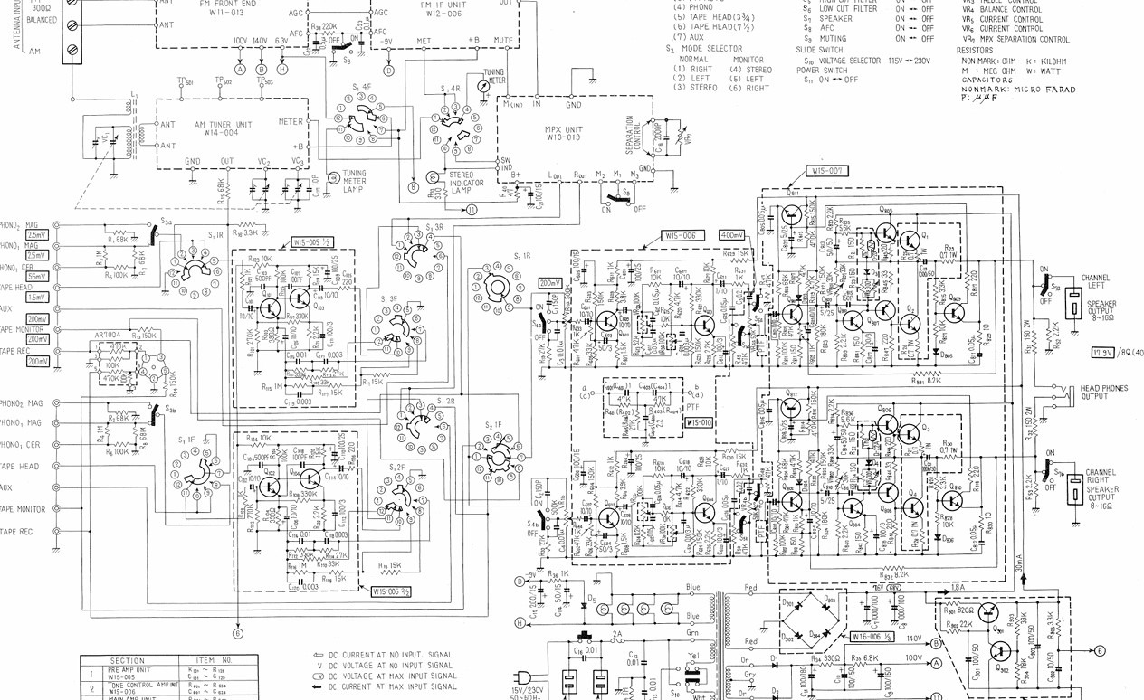
Here are the schematics and detailed user manual. The schematics are beautifully drawn in my view and a work of art in themselves.
I bought my Gyro SE (SE for ‘Spider Edition’) in 2016, having read about Michell turntables on and off for more than 20 years. While working in Taiwan between 2011 and 2015, I visited a local Audio shop in Tianmu, Taipei where a full Gyrodec was on display. It was a huge piece of machinery in its acrylic cabinet, and one could not help but admire the beauty of the thing – affordable British precision engineering at its very best. I returned to the UK at the end of 2015, after a stint in Shanghai, and finally bought a Gyrodec SE in 2016. A local audio store in Norwich assembled the beast for me and I duly got a call to let me know it was ready to be collected. I can tell you I was way more excited than I was getting a new car!
My turntable came with a bog standard Rega arm that I used with an Ortofon Black MM cartridge with a Shibata stylus for a year or two (there’s a whole back story to this specific cartridge as well – one for another post) until I was able to find a mint SME 3009 II ‘Improved’ on eBay which I still have and use with a Denon DL103 MC cartridge. Some may criticize my SME arm + DL103 pairing, but I haven’t had reason to doubt the sound is anything but sterling. The folks at Michell were helpful in guiding me through the process of converting the standard arm mounting plate to a new one that catered for the SME arm.
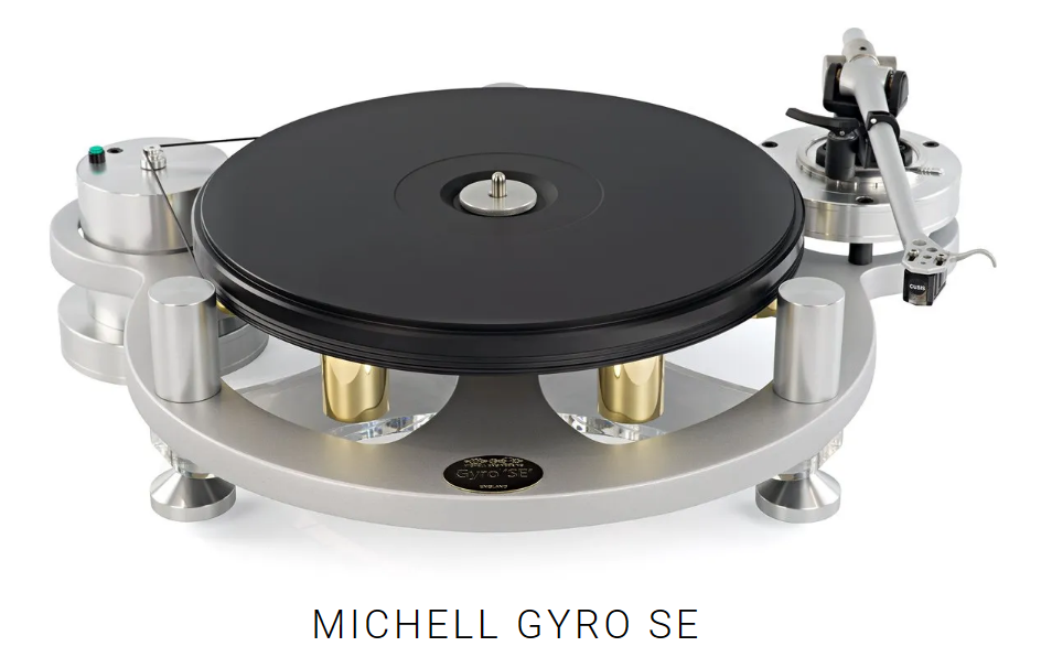
As of 2025, the Michell Gyrodec, and the various progeny (Orb, Gyro SE and associated upgrades) have been around in their current form for 30 to 40 years. The Gyrodec was launched in 1982 and, in the words of Michell ‘turned turntable design upside down’. The fact that this iconic turntable, and its various derivatives, is still available decades after launch, wowing reviewers and buyers alike, stands as testimony to the quality and robustness of the original industrial design and engineering. Over the intervening decades, the Gyrodec and Gyro SE have gradually been improved with better materials and manufacturing tolerances so that today, in 2025, you have a topflight product that can compete with turntables costing 2 or 3 times as much. The finished products are heavy, robust and the finish is superb.
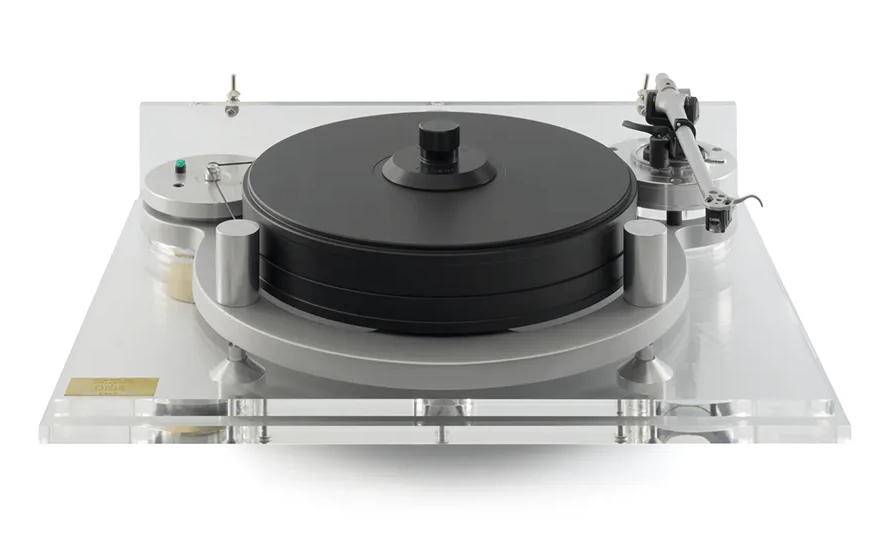
Pictured above is the Michell Orb shown without its acrylic lid.
In 2016 when I bought my Gyro SE, they were priced at £1750 with the basic Rega arm. That same table now retails at £3500, and if you go for its bigger brother, the straight ‘Gyrodec’, you are looking at £4500 with a better arm. Part of this of course is due to increased demand for high-end turntables as audiophiles have come to recognize the special qualities vinyl brings to the listening experience, but another reason I believe, is that Michell have come to the realisation that in a world where everything is made of tacky plastic and pressed plywood, a beautifully designed and engineered product that has stood the test of time can and should demand a premium. The other great thing about the Michell turntables is you can start with a basic Gyro SE and then over time upgrade it, so you end up with a top-of-the- range Gyrodec. This would entail replacing the platter and then perhaps later adding the acrylic base and plinth, and of course whatever arm takes your fancy.
What does a Michell Gyro SE sound like? Michael Fremer, of Stereophile fame, reviewed the Gyro SE in 2000 and then again just a few years ago, describing the turntable as producing ‘airy highs’ and in the latter review, ‘solid crisp, bass’. In my system, over KEF LS50s’ or my B&W 703s’, I’d describe the sound as lush and expansive, with a clean, extended sonic palate right across the audio spectrum. With a Michell, you really are in the company of an extraordinary sounding turntable for the money, no matter what kind of music you play – the preferences in my case lying with late 19th and 20th century classical music and jazz, although I do enjoy Sting and Shaggy’s 44/876 when the mood takes me!
Here is a short video from Michell, talking about the product range and the company ethos https://youtu.be/KtcsXCB1Fc4
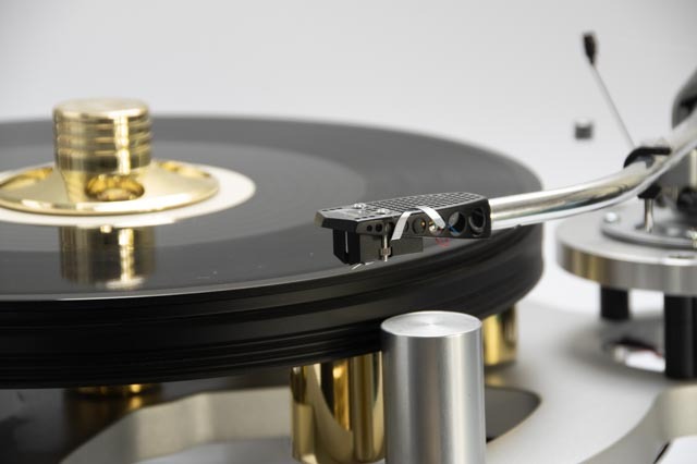
Below, are some pictures of my Michell Gyrodec SE and the equally stunning SME arm with my X-Altra MC/MM phono preamp. In normal use, the turntable sits on an Atacama stand upon which I have placed a 40kg block of polished granite which in turn is isolated from the stand via 4 very large rubber bumper/shock absorbers. This decouples the turntable from any extraneous vibration from a very low frequency.
You can also order a complete ax-amplifier PCB bundle here which gives you all the PCBs used in the original amplifier as described in the audioXpress articles.
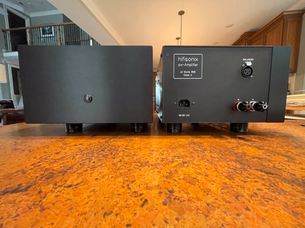
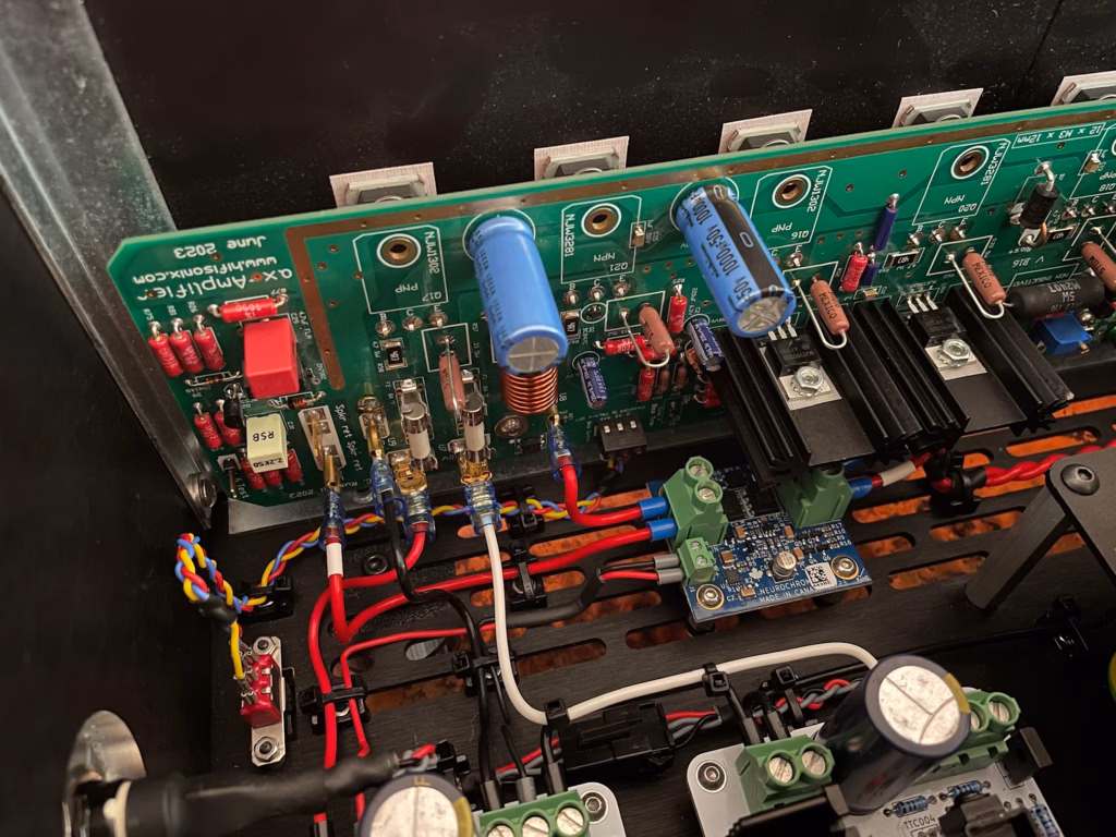
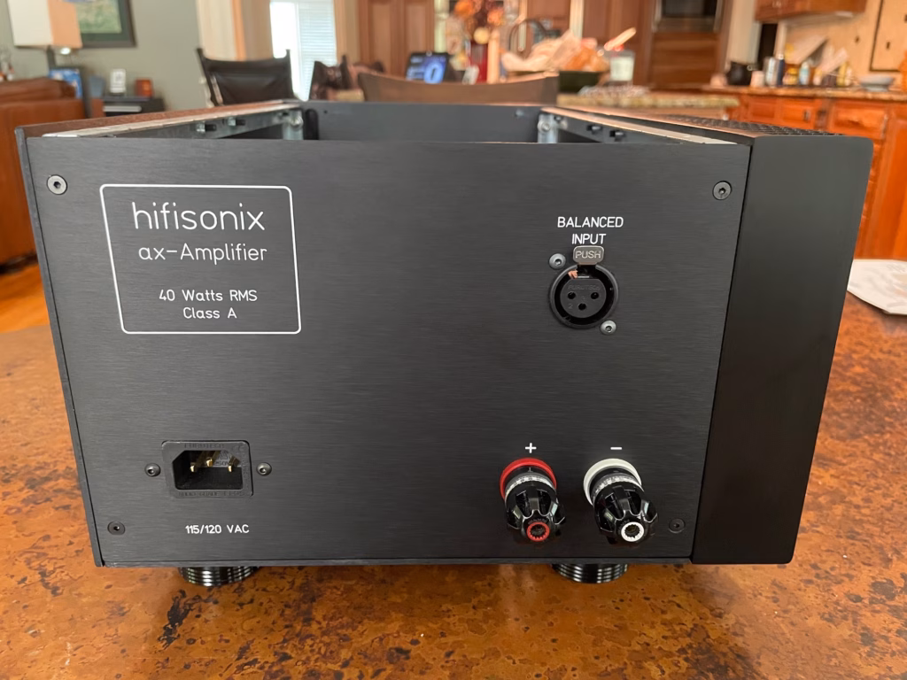
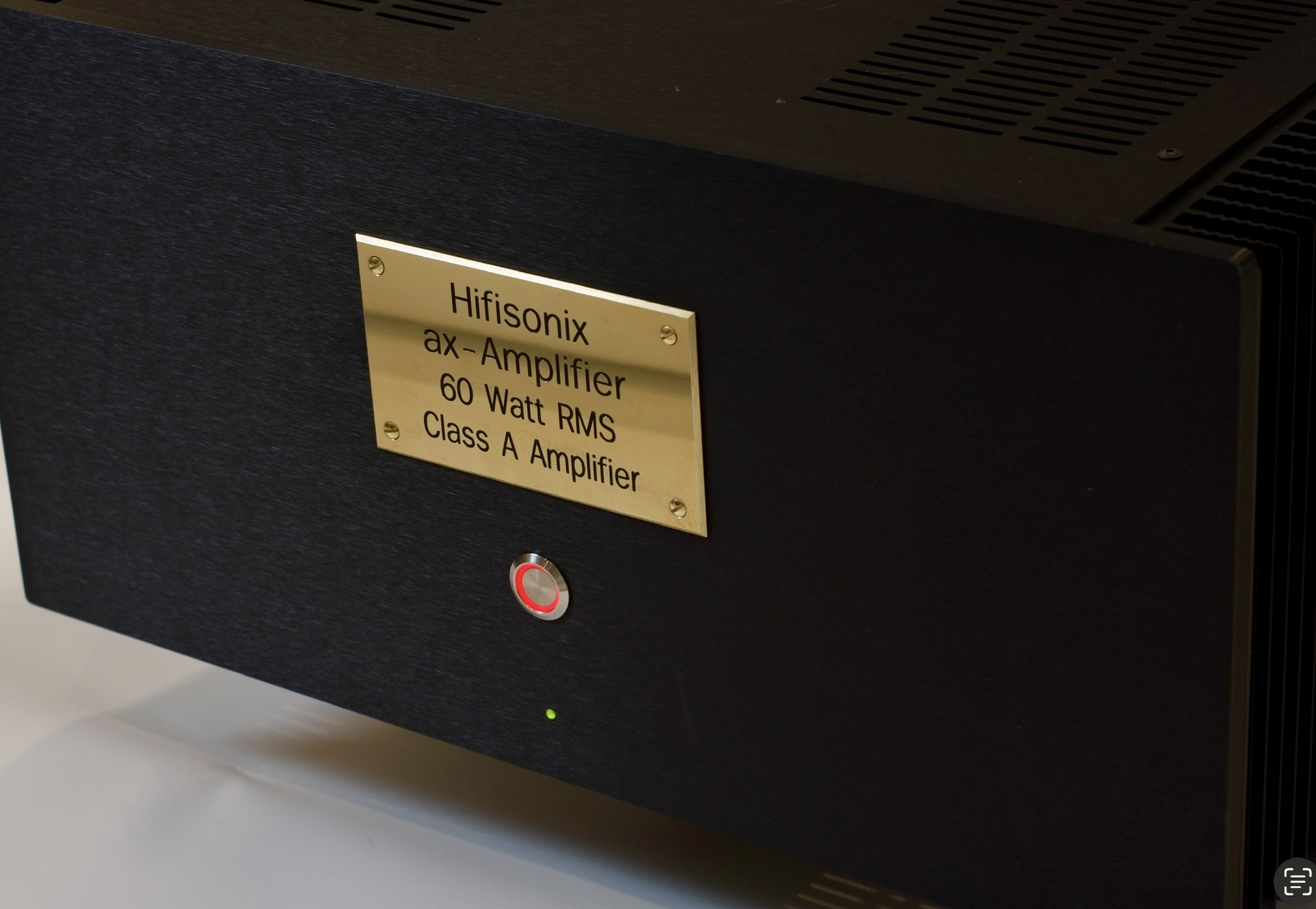
The ax-Amp is a topologically simple 60 W RMS per channel (140W peak class A at <7 ppm distortion) class A current feedback amplifier employing Augmented Feedback Error Correction (AFEC) which I first described in 2012, to achieve ultra-low distortion, very high PSRR and low DC offset. Direct regulation of the class A output standing current results in stable bias over the full operating temperature and all three bias modes. The design uses 4 pairs of 200 Watt sustained beta output transistors per channel to manage the thermal dissipation and allow the amplifier to comfortably deliver peak load currents of >26A. At the rated 60W RMS power, 1 kHz distortion into 8 Ohms measures 3.5ppm, almost all of that contributed by the test instrumentation, while into 2 Ohms, delivering >220 Watts, the distortion is just 12 ppm. The 19+20 kHz full power IMD 1 kHz residual is -118 dBr, attesting to the ax-Amplifiers very good HF linearity. The 8 ohm load full power mains noise floor peaks are better than -126 dBr. Using a small 3 position (ON-OFF-ON) toggle switch mounted on the chassis underside just behind the front panel, the amplifier can be switched to class A, class AAB or class AB. To save power, a fast response ‘plateau’ bias circuit switches the amplifier to class A or AAB operation (if selected) when input signal is detected and reverts it to class AB operation 40 seconds after the absence of any input signal.
Here is a quick teaser of the Part 1 article as it appeared in audioXpress: –
The ax-Amplifier uses the diyAudio.com deluxe 5U chassis that comes with predrilled heatsinks and drilled rear panel. US builders can order the chassis from diyaudio.com, while European builders can order the chassis directly from Modushop in Italy, specifying ‘diyAudio 5U deluxe chassis’. Here is the enclosure. When ordering the chassis from Modushop, be sure to specify ‘diyAudio pre-drilled hole specification’.
I have done a lot of listening with the ax-Amp to a wide range of music covering jazz, classical and rock on KEFLS50s paired with a B&W sub, B&W 703s (the big originals back from 2003/2004) and Dali Oberons. The bass is clean, and goes exceptionally deep which is great for rock and fusion jazz, but that is matched with a fantastically open and detailed mid-range and a delicate, expansive top end, particularly evident on the LS50s. I have a penchant for 19th and 20th century classical music, for example Stravinsky’s Firebird Suite and Sibelius’ 3rd, 4th and 5th symphonies. This complex, multilayered music, demands clean open amplification free of IMD and harmonic distortion of any sort if every nuance in the recording is to be reproduced faithfully. Claudio Abbado’s LSO recording of the Stravinsky Firebird Suite emerges out of absolute silence, followed a few minutes later by the climactic crescendo at the end of the first movement that demands huge reserves of power, dynamic range and soundstage breadth, all of which the ax-Amp reproduces confidently and with the utmost finesse, no doubt a lot of this resting on the class A bias. My musical journey into jazz covers everything from Ella Fitzgerald, Chick Corea through to Miles Davis and Dave Brubeck. On playback with jazz recordings, and especially small ensembles, I look for the space between the musicians which creates that 3D ‘being there’ sonic canvas, and Brubeck’s ‘Take Five’ 1959 recording on the album ‘Time Out‘ has this in bucket loads which the ax-Amp delivers superbly through the KEF LS50’s. Many of Chick Corea’s early recordings like ‘The Mad Hatter‘ (1978) hint at over-zealous compression by the recording engineer but are nevertheless well recorded and sound at their best through the B&W 703s which are able to reproduce the ‘in your face’ musical experience. Again, the ax-Amp is able to reproduce every nuance and instrument with clarity and when required, the power this genre demands.
Physically, this is a BIG, imposing, amplifier weighing in at about 23 kg (50 lbs). It isn’t a cheap amplifier to build, but it will look the business in any system, and most importantly deliver the goods no matter what type of music it is asked to reproduce. The ax-Amp is best suited to medium efficiency speakers of around 86 dB or better sensitivity in average sized living/sound rooms which will enable it to confidently reproduce orchestral crescendos. My build used 10mm feet to ensure the amp stood well off the ground, allowing good air circulation. After continuous use for about an hour, the heatsink temperatures will be about 56C, with the ambient at c. 21C. As discussed in the technical write-up, the plateau bias circuit means the amp will revert to class AB if no music is detected for 40 seconds or more, and switch back to class A in about 2-3 milliseconds when it detects a music signal. It should be noted when operating in class AB, the ax-Amp will deliver about 2.4W peak class A before transitioning to class AB, and in class AAB, the first 11.5 W are in class A – so it is very generous with the class A operation.
As always, if you have any questions, I’ll be very happy to answer them and provide any technical support or other enquiries you may require should you decide to build the ax-Amplifier.
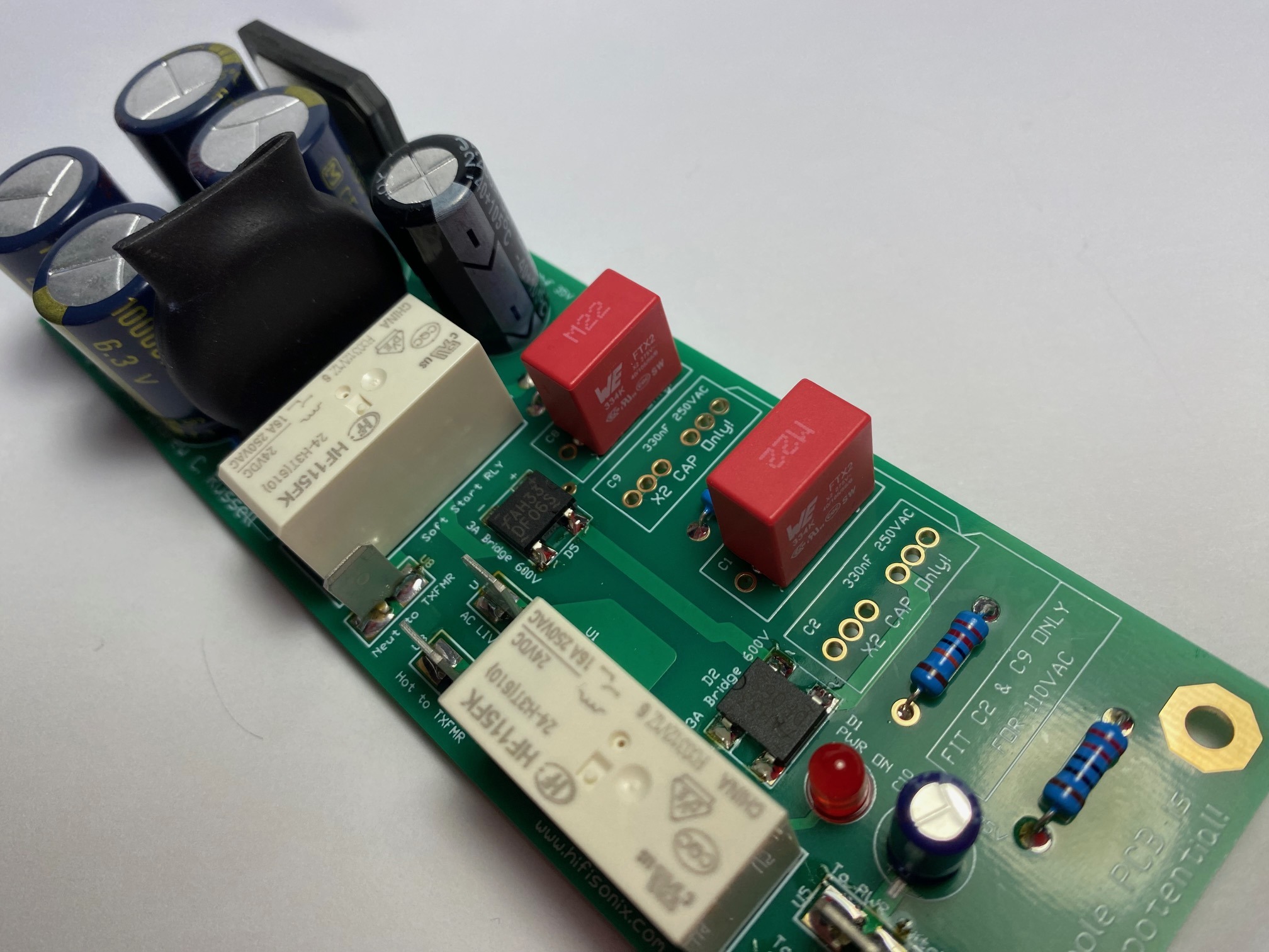
The original Soft Start + DC Blocker published on this website a few years ago required quite complex wiring encompassing both the mains supply to the transformer and wiring from the rectified and DC-smoothed secondary. Additionally, the mains power switch had to be rated for the full primary AC load current which placed severe limitations on builders looking to find an attractive switch that looked good on a power amplifier front panel. These issues, rightly, put many constructors off and they looked elsewhere to solve their power ON/OFF, in-rush current, and mains DC offset problems.
Offering a neat, easy-to-assemble solution, the new Hifisonix Improved Soft Start + DC Blocker + Power On/Off Controller aka iSSDCB overcomes all of those problems:-
Greatly simplified wiring required only on the mains supply side of the transformer
Double the full AC mains load capability of the original SSDCB – 4.6A vs. 2.3A
Allows use of attractive anti-vandal power control switches – max required switch current rating is 30mA DC – for full ON/OFF power control
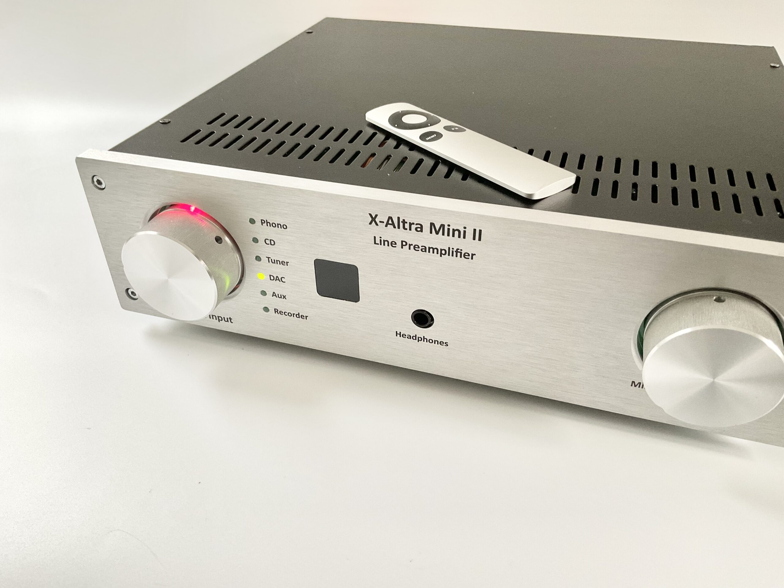
The X-Altra Mini II has been discontinued as a complete project. The individual PCBs are still available over in the shop however and are great line stages and power supplies. The X-Altra Mini II is a superb preamplifier and it sits at the heart of my system, but it was complex with lots of inter-module wiring and I think that put some builders off. There is a new preamplifier coming – tentatively called the X-Altra Mini III – that places everything on one PCB (PSU, headphone amplifier, phono amp, line stage etc). A single ribbon cable connects the main analog board to the controller board. It offers exactly the same functionality as the original design but is easier and much cheaper to build – stay tuned for updates!
The rest of this post discusses the listening tests I conducted on the original X-Altra Mini II back in 2022.
X-Altra Mini II Listening Tests
I conducted listening tests using an Oppo BD103 CD player and an external phono source (X-Altra MC/MM Phono EQ Preamp published in audioXpress Feb and March 2021) for all three vinyl recording assessments and on one of the vinyls, I also listened to the X-Altra Mini II internal MC/MM EQ preamp board. The discrete line stage is open with a fantastically smooth sonic signature that is quite different from the AD797 commercial preamp, despite both preamplifiers measuring well under 10ppm distortion and with measured hum and noise at or below -120 dBV ie inaudible. The measured X-Altra Mini II spot noise floor is c. -140 dBV and so it is exceedingly quiet with no discernible hiss from the speaker tweeters. The -3dB bandwidth of the Model 1501 is c. 200 kHz while the X-Altra Mini II is 130 kHz. I have to point out that my hearing is not that of a young person – but HF is just one part of the overall listening experience with things like imaging, bass extension, midrange articulation etc playing equally, if not more, of an important role.
I used my kx2-Amp (class A 15W RMS, 28-Watt peak class A ) and Dali Oberon 5, B&W 703 and KEF LS50s’ to do the listening evaluation and the smooth, open sonic signature is consistent across all three speakers. The X-Altra Mini II brought the venue and the artists into my listening room unlike any of my previous system setups. The imaging is absolutely outstanding on the X-Altra Mini II – one of my go to test CD’s for this is Fourplay’s eponymous CD that features fantastic left to right width and back to front sound stage depth. This of course has a lot to do with the speakers and the recording, but if the electronics are subpar in any way, they will not support the illusion that the sound is not coming from the speakers themselves – you really want to be able to close your eyes and not be able to point to a speaker source but rather individual instruments laid out left to right and front to back. The top end is smooth and silky with no hint of sibilance. This is the first discrete JFET line level design I have done, and I think the JFET front end plays an important part. I also listened extensively to Chick Coreas’ (RIP) ‘Super Trio’ CD recorded in 2005 by Chet Himes and Bernie Kirsh. This is a superb live recording with great bass extension and a wonderful soundstage and lots of excitement and sonic fireworks on display which was faithfully conveyed by the X-Altra Mini II.
For the vinyl assessment, I listened to three recordings – ‘Ella Fitzgerald Sings the Irving Berlin Songbook‘, and two Chick Corea recordings from the 1970’s – ‘Mad Hatter’ and ‘The Leprechaun‘. Out of the three, the Ella Fitzgerald recording is the best (I’ve written about it here). On the Ella Fitzgerald recording, the X-Altra Mini II conveyed the sense of weight in the lower registers with an effortless, open sound in the mid-range and top octaves, especially noticeable on brass. Images were precisely placed on the sound stage, extending well beyond the edges of the speakers and a long way back behind them. On this particular recording, I also listened using the X-Altra Mini II MC/MM preamp board and whilst not quite in the same league as the stand-alone X-Altra MC/MM preamp, the overall sound was nevertheless superb and still quiet for an opamp based MC preamplifier. The Chick Corea recordings don’t really lend themselves to trying to assess sound and stage tonal quality in the same way the Ella Fitzgerald recoding does. They however are exciting recordings with a lot of propulsive bass, ethereal vocals (courtesy Gale Moran) and drum kit fireworks from the inimitable Steve Gadd. The preamp conveyed the excitement of the recording with great pace, attack and timing.
A few words on the headphone amplifier are in order. The X-Altra Mini II uses the HPA-1 class A headphone amp and my iteration has the OPA1642 dual JFET opamp (although you can also use an LM4562 or NE5532 as discussed in the HPA-1 write-up) driving a MJE15032/33 push-pull output stage biased at 90mA into class A (180mA peak class A current), so it will deliver 1.75 W in class A into a 32 Ohm pair of headphones. I use 12 year old Audio Technica ATH AD900 ‘Air’ headphones I bought in Japan which are not particularly bassy but have the best imaging, midrange and top end I’ve heard bar the Stax tube driven electrostatics – they really are quite special in my view. Through the phones, the preamp retains its open, smooth sound, again without any hint of harshness or sibilance in the top registers. Since the headphone amplifier output impedance is very low, the bass is crisp and goes much deeper than is the case with large diaphragm, open back headphones driven from high impedance resistive dividers. The dedicated, low impedance output headphone amp makes a huge positive impact on the sound.
The addition of two unbalanced (one main and one auxiliary) outputs in addition to a pair of balanced outputs means that with this preamp, I can now have both my power amps (kx2 and Model 1721 240-Watt power amplifiers) along with the sub bass permanently hooked up without recourse to cable swapping or special split cables – so it’s really convenient. The kx2 drives the Dali Oberons and the KEF LS50’s, and the Model 1721 the B&W 703 with the sub bass switched on with the KEF LS50’s.
The picture below is of the ‘Classic’ version of the X-Altra Mini II.
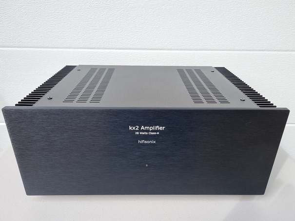
The 15W RMS (28W peak class A) kx2-Amplifier offers outstanding noise and distortion performance and is specifically designed for driving high efficiency speakers in average to large listening spaces but also performs well driving more normal efficiency speakers in restricted listening spaces.
Whether you are an experienced audio equipment constructor looking for the ultimate small amplifier to drive your horn speakers, or new to the game and looking for an introduction to class A solid state amplifiers, the kx2-Amp is the perfect answer to your search. As always, I am on hand to help you through your build process.
The kx2 features very low distortion (see the build doc linked to above for a full set of measurements) and uses TMC (‘transitional miller compensation’). By opening a jumper on the PCB, the compensation can be changed to standard Miller compensation which some people prefer. On the kx2, the output operating mode can be switched between class A, class AAB or class AB in similar fashion to its larger brother, the ax-Amplifier, by means of a 3-position toggle switch located on the underside of the amplifier just behind the front panel.
Careful attention to the PCB layout and routing of some tracks resulted in a dramatic 15 dB reduction in the measured noise floor compared to the sx-Amp which was first published way back in 2012. In class AB mode, the noise floor -120 dBr reference 15W RMS into 8 Ohms, and in class A mode -115 dBr 15 W RMS into 8 Ohms (inputs shorted to signal ground in both measurements).
The OPS bias is controlled with a single transistor servo that maintains the DC operating conditions to within 3% over the full operating temperature range (15C through to >60C).
The version you see in the image above was built in a housing that I originally purchased in Taipei when I lived there. I had a new top plate fabricated by Schaeffer AG in Germany in 2018. For UK builders, there is also the option in the UK of Meface Ltd, but the maximum panel thickness is 3mm.