This series of articles on TIM and SID (and subsequent AES paper), were authored by Walter G. Jung and published between 1977 and 1979 in ‘The Audio Amateur’. It should be read in the context of amplifier design as it stood in the late 1970’s: a clear understanding of the mechanism was only just beginning to emerge, and regrettably, many practitioners ended up incorrectly blaming the root cause of the problem on feedback, which of course we now know it is not. It took another 5 to 10 years after this paper, and Bob Cordell’s 1980 paper, before an engineering approach that prevented TIM and SID entered the audio mainstream. Today, in 2018, designing amplifiers that do not suffer from these problems is easy and very few if any current commercial offerings have these problems.
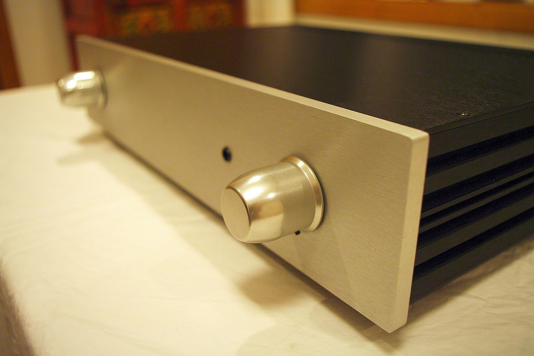
The X-Altra Mini One is a simple line preamplifer based on the National Semiconductor LM4562 (also known as the LME49720) that I built around 2008 and which served me well until about 2014 when it was replaced with newer more sophisticated designs. Nevertheless, this simple preamp sounded very good, and thanks to the LM4562 (which was quite new back then), the distortion is very low. I would characterize the sound as warm, open and pleasingly rounded.
On big power amplifiers, conventional electromechanical relays leave much to be desired when it comes to their ability to reliably switch fault level currents in the event of a catastrophic amplifier fault. In a worst case situation (and I speak from experience), one of the output devices fails short circuit, placing the full amplifier rail voltage across the loudspeaker terminals. Relay switching capability falls off rapidly with the increase in DC levels, and in the scenario just posited, will usually fail short circuit, with the contacts welding together. Most speakers will only tolerate this type of abuse for a few 10’s of milliseconds before they are irreparably damaged. The design presented here covers the relay function, and some ideas on overcurrent protection and related circuits, overcomes all of the conventional EM relay shortcomings by employing low Rds(on) mosfets arranged as a a bi-directional (i.e. AC) switch. The design can switch fault level currents of 50 A. Furthermore, unlike relays, there is no wear out mechanism.
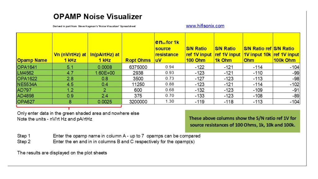
This Excel spread sheet tool was developed from one by Steve Hagman (www.AnalogHome.com) and allows en and ien data for up to 7 opamps to be compared. When using the tool, make sure you enter comparable data – so for example, always use the same frequency to make the comparison. I normally use 1 kHz worst case data. For LF noise (where 1/f noise usually dominates and an important consideration for phono equalizers), most manufacturers quote figures at 10Hz, so make sure if you are looking at LF noise data, you use similar frequency point data to make a fair comparison. The tool also contains a system level noise modeller, that allows a signal chain of up to 4 stages to be analyzed, and the resulting S/N ratio and equivalent noise resistor to be calculated.
(The tool was updated 2nd February 2020 after errors were noted by some users)
The definitive document on noise analysis is the classic National Semiconductor AN104 ‘Noise Specs confusing?’ which you can download here AN-104
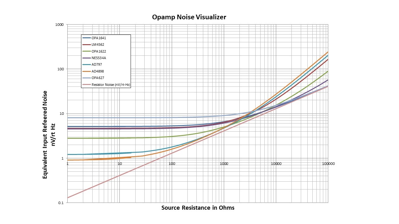
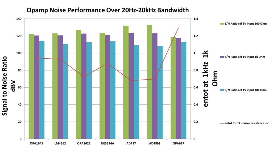
Below are some screen shots of the Noise Visualizer output.
Data Entry Screen. You Can Enter Data for Up to 7 Opamps to CompareS/N Ratio Comparison Output Plot of the Selected Opamps at Rsource = 100, 1k and 10k OhmsNoise Visualization for the Selected Opamps Showing en(tot) vs Rsource
Here is the result of my investigation in to a fully balanced high performance, low distortion line pre-amp, the ‘Ovation’ Stereo Control Amplifier One’.
I drew some inspiration for this project after reading about the TEAC Esoteric line preamp, which is also based on the TI PGA2320, and received rave reviews from the hi-end press. Esoteric have stuck with the PGA2320 in subsequent models of their line pre-amp and continued to garner excellent reviews. Michael Fremer, of Sterophile fame, said it was one of the best line preamps he had heard at any price – the Esoteric goes for about $10k.
How does my SCA-1 sound? Very open with a smooth mid and upper range. DC coupling throughout means there are no nasties in the LF area either, and overall imaging is excellent.
This design is a dual mono fully balanced line pre-amp. Input balanced source selection is via relays, under CPU control via a serial optically isolated bus. The output from the source selection feeds into a dual LM4562 high resolution audio op-amp buffer, and this then feeds into a TI PGA2320, which is configured as a balanced volume control stage. The balanced output from the PGA2320 feeds into an inverting stage configured around an LM4562, with each half of the LM4562 driving an LME49600 buffer. The LM49600’s are inside the LM4562 feedback loop in order to minimize distortion. Since this pre-amp is DC coupled from input throught to output, a servo configured around an AD8512 dual op-amp ensures output offsets are limited to around 200uV worst case.The headphone amplifer is built around an LME49710 high resolution audio op-amp, and the LME49600, again, the buffer inside the op-amp’s feedback loop for the lowest possible distortion.
The entire pre-amp is controlled by an NXP LPC1768 32 bit ARM controller from mbed (see www.mbed.org). The controller is fully optically isolated from the main analog board in order to ensure there are NO noise problems, with separate optically isolated serial busses for each channel. The operating program is written in C and ended up at about 120k bytes including the graphics (the actual I/O part is about 20k bytes long) and is interrupt driven, so when not executing commands from the front panel controls or the remote control, the CPU shuts down, minimizing noise and power consumption. Of course, the use of the optically isolated serial bus also has a big impact on noise performance, where I am aimed for something well under -110dB worst case.
Ever wondered how we got to ‘feedback is bad’, ‘ . . . sampling destroys the music’ or ‘ . . . analog is 40 bits resolution . . .’ , ‘we need damping factors of 1000’ and ‘ . . . only vinyl sounds good’ ? Tom D Kite PhD, of Audio Precision, takes us on a journey through the myths and then home to the real facts . . . AudioMyths
Here are some other useful application notes and articles that may help in developing an understanding of amplifier topologies and their associated trade-offs.
This design, which I completed in 2010, takes an LM4562 and marries it to a hefty single ended class A output stage, which can be biased up for either 50 mA or 110 mA. The output stage is included in the global feedback network and can achieve 1 ppm at 20 kHz into 600 Ohms at 3V Output, and about 10 ppm at 10V out into 600 Ohms at 20 kHz.
With the output bias set to 110 mA, this buffer also makes a fine high end headphone amplifier, allowing up to 3 V peak into 32 Ohms, whilst still remaining in class A with ultra low distortion.
![relay[1]](https://hifisonix.com/wp-content/uploads/2012/07/relay11.jpg)

")
")

