Blog

  • Augmented Feedback Error Correction (AFEC)

    Augmented Feedback Error Correction (AFEC)

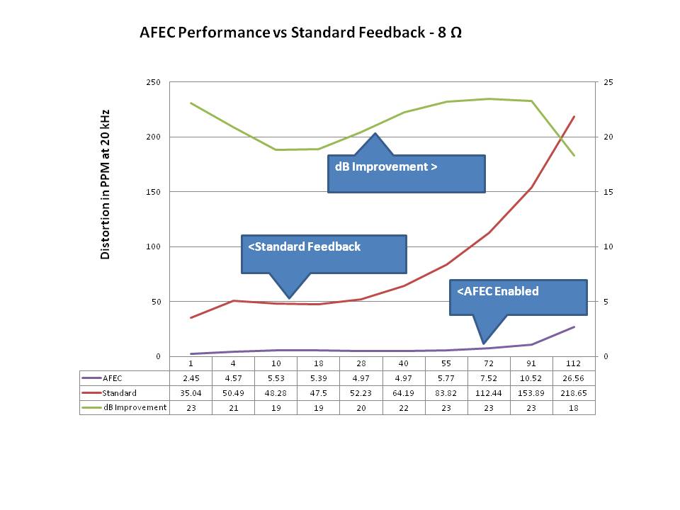
    AFEC is a simple technique that augments the feedback of an amplifier to dramatically improve the Large Signal Non-linearity (LSN) distortion performance by up to 20 dB across the audio band. Additionally, AFEC acts to remove any DC offsets and also improve PSRR significantly.

    Augmenting the feedback in a manner similar to that described in this document has been tried previously – the first example is from the early 1980’s at Hitachi. However, the technique never entered the mainstream – one can only postulate that lack of very high performance opamps (bandwidth, SR and distortion performance), along with the difficultly of being able to characterize such a system for stability modeling purposes (as we can do now on LTspice for example) were contributing factors to its early demise. However, as of 2012, these problems are now solved, so perhaps we shall now see the return of AFEC as a viable distortion reduction technique.

    You can download the article here AFEC-V3.0

    Excerpt

    One of the advantages of CFA power amplifiers is their very high slew rates (200+ V/us is not uncommon), but loop gains tend not to be as high as VFA topology designs. This is fine at low to medium signal levels, where the very good front end linearity and wide loop gain bandwidths of CFAs’ manifest as low distortion; however, at higher power output levels where the output stage and TAS/TIS LSN starts make itself felt, CFA distortion is generally worse, and this is as a direct result of the lower loop gains – note, I am talking here about minimalist CFA topology designs. Cross over is the major type of distortion in class AB amplifiers and there have been various schemes invented to deal with this over the years – most relying on feed forward techniques (see Peter Walker’s Quad Current Dumping for example, or Michael Renardson’s MJR7 design). AFEC does a good job of reducing cross over distortion artifacts, and in particular, those arising from OPS bias current shifts, but it will not compensate for an under biased OPS where there is a clear discontinuity in the crossover region. CFA amplifier PSRR is lower than VFA. This usually necessitates a front-end stage regulator – but even then, the best designs are still usually 20~30 dB below that of VFA exemplars. It will be shown that AFEC can improve CFA PSRR such that it matches or exceeds VFA PSRR, whilst at the same time removing any output offsets as a result of the servo action of the AFEC control amplifier.

  • Output Coupling Inductors

    Output Coupling Inductors

    Inductors on the output of an amplifer are used to isolate the amplifer from capacitive loads at HF and ensure stability.  There has been quite some debate on DIYaudio.com as to whether they are audible, necessary, or just the result of designers being overly cautious.  Some very well known designers in the field have decided against using output inductors.    In this short presentation, I explore the pros and cons.


  • Oscillation Sniffer

    No ‘scope?  This simple circuit can help you quickly see if you have any oscillation problems on your opamp or amplifer circuit.

    Note, its NOT designed to be connected to high impedance nodes.

    Oscillation Sniffer by Bonsai


  • H.S. Black: Feedback

    Feedback, or its application by humans as control theory, despite the protestations of audio designers that eschew its use, is an entirely natural phenomena. Every time you reach out to pick up an object, get up and walk around, or write something on a piece of paper, feedback data from multiple body sensors are being processed by your brain so that your immediate objective can be executed flawlessly and without error. And, here we have not even begun considering the complex bio-chemical metabolic pathways within the human body – or every single other life form on the planet for that matter – that rely on multi-loop, self-regulating (i.e. feedback control) behaviour.  Nature abounds with examples of the miracle of feedback – a bird in flight, the earths weather system (human CO2 emissions notwithstanding), the thermonuclear reaction taking place in the core of a stable main sequence star, and even planet wide climatic control as exemplified by James Lovelock’s Gaia Hypothesis and so forth. It may therefore be more correct  to say that humans discovered feedback but did not invent it.

    H.S. Black  published this article about feedback in the Bell Labs in house magazine ‘The Bell Laboratories Record’  in 1934, based on work he had done on the subject starting as early as 1927. In it he explains how feedback can be used to improve the performance of repeater amplifiers. Feedback has been described as the most important development in electrical engineering in the 20th century.

    Feedback has been thoroughly and completely explored and codified over the last 80 years resulting in a huge body of published scholarly work across many hundreds of application fields ranging from aerodynamics, power generation, consumer electronics and onto process control in chemical production and self-regulating metabolic processes in the life sciences.  It is no exaggeration to say that our modern world would not function without it, and neither would mother nature.

    Next time you board an airplane, rest assured you will only be arriving safely at you destination because there are hundreds of inter-linking feedback loops all operating flawlessly – from the airplane ailerons, tail fins, pressure sensors to the jet engine turbine control systems and on to navigation and guidance and so forth. Audio amplifiers in this context, and within the natural world,  are therefore an exceedingly simple application of  the science of control theory aka feedback.   

    Bell-Feedback


  • Measuring TIM

    This paper by Leinonen, Otala and Curl investigates the measurement of TIM, a hot topic in the 1970’s and early ’80’s after its potential to cause sonic degradation by the incorrect application of feedback around high loop gain solid state amplifiers.

    Now days (2017), there is a very complete and thoroughly in-depth understanding of TIM and related SID and how to ensure it can never take place. Modern VFA amplifiers overcome TIM by ensuring the front end gain stage gm is low (enough) and  there is sufficient current provided by the input stage of the  the amplifier  to quickly charge the integrating compensation network around the TIS. Further, new compensation design techniques such as TMC, OIC, TPC  (see Bob Cordell’s book ‘Designing Audio Power Amplifiers’ for more details) allow large amounts of feedback to be applied around amplifiers with improved sonic fidelity and none of the problems early solid state amplifiers were plagued with.

    Measuring TIM.pdf

    For a discussion around this topic and an overview of how the audio industry solved the TIM/SID problem,  take a look at ‘Solid State Feedback Amplifiers: A short History’


  • A Concise Overview of TIM by Bob Cordell

    This set of articles was written in the early 1980’s by Bob Cordell, a few years after Matti Otala identified TIM (Transient Inter-Modulation) as the probable cause of sonic imperfections in high feedback solid state amplifiers in the 1970’s.

    Otala’s paper sent shock waves through the amplifier design community but sadly it ended up ‘subjectivizing’ amplifier design:  instead of it being treated as an entirely science-based activity, it subsequently became corrupted with folklore, voodoo engineering, snake oil and plain misinformation that demonized feedback as sonically bad and the cause of the ‘solid state sound’ and TIM which of course it is not. The result is many hundreds of  commercial designs that are sub-optimal through lack of it, or through the incorrect application of it. Unfortunately, the problem still persists  –  you can pick up  an amplifier brochure or go on a commercial website where the vendor proudly boasts about their  ‘zero feedback’ products that feature high distortion, load dependent frequency responses and the inability to drive some loudspeakers.

    Bob Cordell’s exposé below delves into the finer details of TIM and lays out clearly and succinctly how to avoid it without having to discard feedback which is without doubt one of the most useful tools available to any amplifier designer.

    Another View of TIM I

    Another View of TIM II

  • The Monolithic Op-Amp: A Tutorial Study

    The Monolithic Op-Amp: A Tutorial Study

    This was an invited paper at the ISSCC in 1974 by James Solomon, who at the time worked for National Semiconductor (acquired in 2011 by TI). Those were heady days in semiconductors, with major process and circuit design breakthroughs taking place at breakneck speed. The general-purpose microprocessors’ pivotal role in powering the Apple II computer (which used a MOS Technology 6502 device) and the ensuing home computing revolution was just a few years away.  Silicon Valley was already a hot bed of innovation with new companies and their star designers and engineering teams popping up every few months.

    The semiconductor revolution spawned the personal computer, the mobile phone and the internet and today, in 2018, it is safe to say that absolutely every convenience and progress in our modern age leverages off semiconductors.

    This paper represents a snapshot of the state of the art in 1974 with respect to integrated operational amplifiers and should be read in that context.  Just ten years prior to this, opamps were all discrete, many still vacuum tube based, bulky and expensive. About two years after this paper, the Bi-FET input LF355/6/7 family was introduced by National Semiconductor with slew rates of up to 20 V/us, and in 1977, the Signetics NE5534 (which was in fact based entirely on the Phillips TDA1034) which featured very low distortion, high slew rates and commendably low noise. Signetics did a much better job of marketing the 5534 than Phillips did on the TDA1034, and it quickly established itself as the premier low signal level audio opamp.  The ‘5534’ as it is known,  remains the workhorse of the professional audio  industry 40 years after its introduction. Other notable opamps from the period were the LM308A that featured very low power consumption and very low input bias currents and the LM301, an improved uncompensated LM741 that allowed wider bandwidths and higher slew rates.  The NE5534 has remained the go to gain block for audio applications ever since the late 1970’s, only being eclipsed in the last 10 years or so by a few devices that have exploited new circuit insights and semiconductor processing breakthroughs.

    James E Solomon Opamp Tutorial.pdf

    The image at the top of this page is that of the LM741 chip

  • Marshall Leach Opamp Tutorial

    Marshall Leach (RIP) was a Professor of Electrical Engineering at Georgia Tech University   best known for his Leach Amplifier which he used as a practical vehicle for teaching his students the finer details of analog design, feedback, thermal compensation and power electronics.  Hundreds of Leach Amplifiers were built over the years by his students, and possibly thousands by DIY builders across the world who came to love not only its fast, open sound, but the elegant simplicity of its design, its legendary ruggedness and the fact that it suffered from absolutely no audible ‘plops’ when powering it up or down.  

    The tutorial below offers a uniquely practical and accessible insight into amplifier design fundamentals from an acknowledged master of the art.

    Op-Amp Tutorial


  • The Alexander Amplifier

    Mark Alexander’s eponymous creation was an early example of a high performance CFA amplifier and used an ADI integrated opamp and IGBT output devices in a novel circuit configuration that, at the time, yielded vanishingly low distortion and blistering speed.  The ‘Alexander’ amplifier has been recycled by practitioners  numerous times since its initial publication with different opamps and mosfets replacing the original IGBT’s. Referenced countless times in publications over the years, it stands as testament to the skill and creativity of its designer.

    The Alexander Amplifier