Your basket is currently empty!
Blog
-
H.S. Black: Feedback
Feedback, or its application by humans as control theory, despite the protestations of audio designers that eschew its use, is an entirely natural phenomena. Every time you reach out to pick up an object, get up and walk around, or write something on a piece of paper, feedback data from multiple body sensors are being processed by your brain so that your immediate objective can be executed flawlessly and without error. And, here we have not even begun considering the complex bio-chemical metabolic pathways within the human body – or every single other life form on the planet for that matter – that rely on multi-loop, self-regulating (i.e. feedback control) behaviour. Nature abounds with examples of the miracle of feedback – a bird in flight, the earths weather system (human CO2 emissions notwithstanding), the thermonuclear reaction taking place in the core of a stable main sequence star, and even planet wide climatic control as exemplified by James Lovelock’s Gaia Hypothesis and so forth. It may therefore be more correct to say that humans discovered feedback but did not invent it.
H.S. Black published this article about feedback in the Bell Labs in house magazine ‘The Bell Laboratories Record’ in 1934, based on work he had done on the subject starting as early as 1927. In it he explains how feedback can be used to improve the performance of repeater amplifiers. Feedback has been described as the most important development in electrical engineering in the 20th century.
Feedback has been thoroughly and completely explored and codified over the last 80 years resulting in a huge body of published scholarly work across many hundreds of application fields ranging from aerodynamics, power generation, consumer electronics and onto process control in chemical production and self-regulating metabolic processes in the life sciences. It is no exaggeration to say that our modern world would not function without it, and neither would mother nature.
Next time you board an airplane, rest assured you will only be arriving safely at you destination because there are hundreds of inter-linking feedback loops all operating flawlessly – from the airplane ailerons, tail fins, pressure sensors to the jet engine turbine control systems and on to navigation and guidance and so forth. Audio amplifiers in this context, and within the natural world, are therefore an exceedingly simple application of the science of control theory aka feedback.
-
Measuring TIM
This paper by Leinonen, Otala and Curl investigates the measurement of TIM, a hot topic in the 1970’s and early ’80’s after its potential to cause sonic degradation by the incorrect application of feedback around high loop gain solid state amplifiers.
Now days (2017), there is a very complete and thoroughly in-depth understanding of TIM and related SID and how to ensure it can never take place. Modern VFA amplifiers overcome TIM by ensuring the front end gain stage gm is low (enough) and there is sufficient current provided by the input stage of the the amplifier to quickly charge the integrating compensation network around the TIS. Further, new compensation design techniques such as TMC, OIC, TPC (see Bob Cordell’s book ‘Designing Audio Power Amplifiers’ for more details) allow large amounts of feedback to be applied around amplifiers with improved sonic fidelity and none of the problems early solid state amplifiers were plagued with.
For a discussion around this topic and an overview of how the audio industry solved the TIM/SID problem, take a look at ‘Solid State Feedback Amplifiers: A short History’
-
A Concise Overview of TIM by Bob Cordell
This set of articles was written in the early 1980’s by Bob Cordell, a few years after Matti Otala identified TIM (Transient Inter-Modulation) as the probable cause of sonic imperfections in high feedback solid state amplifiers in the 1970’s.
Otala’s paper sent shock waves through the amplifier design community but sadly it ended up ‘subjectivizing’ amplifier design: instead of it being treated as an entirely science-based activity, it subsequently became corrupted with folklore, voodoo engineering, snake oil and plain misinformation that demonized feedback as sonically bad and the cause of the ‘solid state sound’ and TIM which of course it is not. The result is many hundreds of commercial designs that are sub-optimal through lack of it, or through the incorrect application of it. Unfortunately, the problem still persists – you can pick up an amplifier brochure or go on a commercial website where the vendor proudly boasts about their ‘zero feedback’ products that feature high distortion, load dependent frequency responses and the inability to drive some loudspeakers.
Bob Cordell’s exposé below delves into the finer details of TIM and lays out clearly and succinctly how to avoid it without having to discard feedback which is without doubt one of the most useful tools available to any amplifier designer.
-
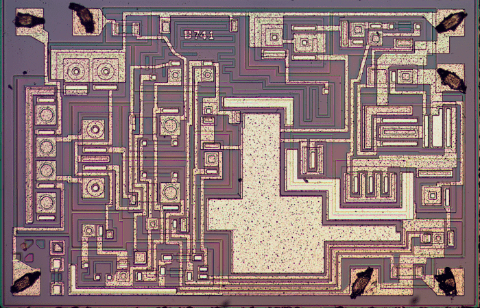
The Monolithic Op-Amp: A Tutorial Study
This was an invited paper at the ISSCC in 1974 by James Solomon, who at the time worked for National Semiconductor (acquired in 2011 by TI). Those were heady days in semiconductors, with major process and circuit design breakthroughs taking place at breakneck speed. The general purpose microprocessors’ pivotal role in powering the Apple II computer (which used a MOS Technology 6502 device) and the ensuing home computing revolution was just a few years away. Silicon Valley was already a hot bed of innovation with new companies and their star designers and engineering teams popping up every few months.
The semiconductor revolution spawned the personal computer, the mobile phone and the internet and today, in 2018, it is safe to say that absolutely every convenience and progress in our modern age leverages off semiconductors.
This paper represents a snap-shot of the state of the art in 1974 with respect to integrated operational amplifiers and should be read in that context. Just ten years prior to this, opamps were all discrete, many still vacuum tube based, bulky and expensive. About one year after this paper, the Bi-FET input LF355/6/7 family was introduced by National Semiconductor with slew rates of up to 20 V/us, and in about 1976 or 1977, the Signetics NE5534 which featured ultra low distortion, high slew rates and commendably low noise. The ‘5534’ as it is known, remains the workhorse of the professional audio industry 40 years after its introduction. Other notable opamps from the period were the LM308A that featured very low power consumption and very low input bias currents and the LM301, an improved uncompensated LM741 that allowed wider bandwidths and higher slew rates. The NE5534 has remained the go to gain block for audio applications ever since the late 1970’s, only being eclipsed in the last 10 years or so by a few devices that have exploited new circuit insights and semiconductor processing breakthroughs.
James E Solomon Opamp Tutorial.pdf
The image below is that of the LM741 chip

-
Marshall Leach Opamp Tutorial
Marshall Leach (RIP) was a Professor of Electrical Engineering at Georgia Tech University best known for his Leach Amplifier which he used as a practical vehicle for teaching his students the finer details of analog design, feedback, thermal compensation and power electronics. Hundreds of Leach Amplifiers were built over the years by his students, and possibly thousands by DIY builders across the world who came to love not only its fast, open sound, but the elegant simplicity of its design, its legendary ruggedness and the fact that it suffered from absolutely no audible ‘plops’ when powering it up or down.

The tutorial below offers a uniquely practical and accessible insight into amplifier design fundamentals from an acknowledged master of the art.
-
The Alexander Amplifier
Mark Alexander’s eponymous creation was an early example of a high performance CFA amplifier and used an ADI integrated opamp and IGBT output devices in a novel circuit configuration that, at the time, yielded vanishingly low distortion and blistering speed. The ‘Alexander’ amplifier has been recycled by practitioners numerous times since its initial publication with different opamps and mosfets replacing the original IGBT’s. Referenced countless times in publications over the years, it stands as testament to the skill and creativity of its designer.
-
An Overview Of SID and TIM, Walt Jung et al
This series of articles on TIM and SID (and subsequent AES paper), were authored by Walter G. Jung and published between 1977 and 1979 in ‘The Audio Amateur’. It should be read in the context of amplifier design as it stood in the late 1970’s: a clear understanding of the mechanism was only just beginning to emerge, and regrettably, many practitioners ended up incorrectly blaming the root cause of the problem on feedback, which of course we now know it is not. It took another 5 to 10 years after this paper, and Bob Cordell’s 1980 paper, before an engineering approach that prevented TIM and SID entered the audio mainstream. Today, in 2018, designing amplifiers that do not suffer from these problems is easy and very few if any current commercial offerings have these problems.
Readers should also read TIM by Robert Cordell
-
X-Altra Mini One Line Preamplifier
The X-Altra Mini One is a simple line preamplifer based on the National Semiconductor LM4562 (also known as the LME49720) that I built around 2008 and which served me well until about 2014 when it was replaced with newer more sophisticated designs. Nevertheless, this simple preamp sounded very good, and thanks to the LM4562 (which was quite new back then), the distortion is very low. I would characterize the sound as warm, open and pleasingly rounded.
Download and read the article here:-
(Please note, there are no PCB’s or Gerbers available for this project.)
-
Hifisonix Solid State Loudspeaker Relay
On big power amplifiers, conventional electromechanical relays leave much to be desired when it comes to their ability to reliably switch fault level currents in the event of a catastrophic amplifier fault. In a worst case situation (and I speak from experience), one of the output devices fails short circuit, placing the full amplifier rail voltage across the loudspeaker terminals. Relay switching capability falls off rapidly with the increase in DC levels, and in the scenario just posited, will usually fail short circuit, with the contacts welding together. Most speakers will only tolerate this type of abuse for a few 10’s of milliseconds before they are irreparably damaged. The design presented here covers the relay function, and some ideas on overcurrent protection and related circuits, overcomes all of the conventional EM relay shortcomings by employing low Rds(on) mosfets arranged as a a bi-directional (i.e. AC) switch. The design can switch fault level currents of 50 A. Furthermore, unlike relays, there is no wear out mechanism.
![relay[1]](https://hifisonix.com/wp-content/uploads/2012/07/relay11.jpg)