A considerable amount has been written about voltage feedback amplifiers (VFA) over the years, but comparatively little attention has been paid to current feedback (CFA) types. Both Robert Cordell and Douglas Self focus almost exclusively on VFAs, with little to no in-depth analysis or consideration of CFAs as viable alternatives to the prevailing VFA-dominated linear amplifier design orthodoxy. I have written extensively about the contortions audio designers went through in the 1960s through to the very early 1990s, as they tried to unravel the vagaries of Lin topology VFAs, to finally arrive at design methodologies that delivered low distortion, adequate slew rates and power bandwidths, while avoiding those worst of all distortions: slewing induced distortion (aka ‘SID’) and transient intermodulation distortion (TIM), or just plain good old-fashioned slew-rate limiting.
It wasn’t until Douglas Self published his first power amplifier design book (known colloquially amongst the audio design fraternity as the ‘APADH’) in the mid-1990s, and the concept of a Lin-topology ‘blameless’ amplifier, that all the key elements required to design and build an excellent VFA were documented and presented logically in a single text – but a well-implemented ‘blameless’ topology amplifier still requires sticking plaster fixes to address its irredeemable flaws. That is not to say others hadn’t taken care of the fundamentals prior to that, but the APADH was the first to put everything an audio designer needed in one document. For example, Robert Cordell produced a very low-distortion VFA in the mid-1980s that also demonstrated a clear understanding of the trade-offs required for good VFA design and addressed crossover distortion employing Hawksford’s novel feedforward scheme in the MOSFET output stage. Additionally, some ten years earlier, James Solomon’s 1974 ISSCC paper also unravelled the power bandwidth versus slew rate and front-end gm conundrum. However, some people just got it plain wrong, and Matti Otala’s claim, best summarised as ‘[high] feedback causes slewing distortion’, led a large contingent of the audio amplifier design community down a path to zero global feedback amplifiers, which are suboptimal in every respect. The real cause of the problem was of course a failure to understand the interlocking mechanisms that define slew rate, loop bandwidth, the required phase and gain margins and how distortion has to be traded off in some cases to ensure stability with any practical load.
However, in retrospect, it is clear with the VFA, the industry was dealing with a fundamentally flawed audio power amplifier topology. Really good solid-state power amplifiers only became readily available in the mid-1990s – in other words, it took a very long time from the late 1960s to the mid 1990s for the industry as a whole to fully understand what they were dealing with. In 2025 it is very much easier to design a near-perfect VFA with ample loop gain, very low distortion, and zero chance of slew-induced distortion within the audio band, regardless of the input source; the methodology and design rules have been thoroughly developed and deployed for at least 30 years.
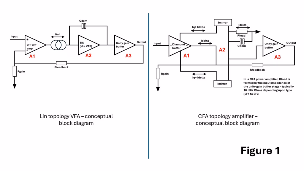
The basic topological configurations of the two amplifier types are depicted in Figure 1 below. On the left is the VFA where the tail current, Itail, which is usually set using a current source of between 2-10mA on modern amplifiers, is ‘steered’ into or out of the A2 integrating stage formed by the TIS around which Cdom (the integrator capacitor) is wrapped. With a sine wave stimulus, the maximum rate of voltage change occurs at the zero-crossing point and the maximum rate of change at any frequency given by (dVout/dt)max=2.π.f.Vp. This can be restated as the minimum required slew rate to reproduce a signal at any required voltage and frequency, so for full power, the required amplifier slew rate (SR) is SR≥2.π.f.Vp, or rearranging, fmax=2.π.Vp.SR. The onset of slewing in a blameless Lin topology amplifier is set by the front-end LTP gm and the tail current, so SR = (2.Pi.Fugf.Itail)/gm where Fugf is the open loop unity gain frequency and the gm is set by gm=Ic.q/kB.T where q is the charge on an electron, B is Boltzmann’s constant, and T is absolute temperature in kelvin. So from this we can conclude that in a VFA, the LTP gm and the tail current, along with the value of Cdom, ultimately set the undistorted power bandwidth. Push the amplifier beyond this point, and the output will start to show signs of slewing. It is important to note here that the slew rate and unity gain open loop frequency are set independently – a high slew rate does not necessarily imply a high unity gain open loop frequency, and vice-a-versa.
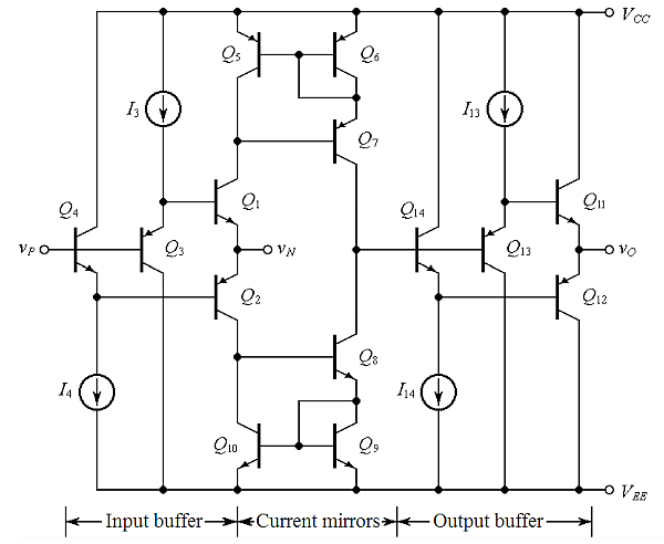
The right-hand side depicts a conceptual model of a CFA. Most of the signal current required to ensure that the inverting input voltage = the non-inverting input voltage flows through Rfeedback and Rgain, with only a small signal related displacement current, Idelta, being added/subtracted to this feedback current flowing in and out of the inverting input. It is this displacement current flowing in and out of the inverting input that gives this type of amplifier its name: current feedback amplifier. We can write this as Idelta = Vinv/Rgain-[Vo-Vinv/Rfeedback]. This displacement current is mirrored by the transadmittance stage (TAS) around A2 and so flows in and out of Rload. Rload is typically just the input impedance of the buffer stage, A3, and in an EF3 power amplifier for example, can confer very high loop gains in power CFAs at LF. The open loop unity gain frequency in a CFA is simply Fugf = 2.Pi.Rfeedback.Cdom. In the diagram, Cdom is shown as going straight to ground, and representative of the total capacitance at the TAS output node which will include the input capacitance to the buffer stage A3, and any other compensation and stray capacitances. You can see from the equation that Fugf can be set with just Rfeedback and/or Cdom – it does not involve the front-end gm in any way. In monolithic IC CFA’s, Cdom is internal to the device (and usually only a few single digit pF), and compensation is set only with the value of Rfeedback. In practical audio power CFAs, the current mirrors are replaced with a symmetrical TIS (aka VAS) stage, generally further raising the open loop gain substantially and Cdom is applied around the TIS in the conventional manner. Idelta peak is usually one to two orders of magnitude lower than the current flowing through the Rfeedback and Rgain setting resistors, and it can charge/discharge Cdom very rapidly. It is for this reason that CFAs do not slew rate limit and offer wide bandwidths and fast rise fall times as a matter of course. On very fast rising signal edges, the peak current into Cdom can be 4 to 8 times the Idelta standing current, in direct contrast to a VFA where the maximum can never be more than the tail current, and it is this current on demand feature that prevents them from slew rate limiting.
To summarise: In a VFA, the current into the integrator stage is set by the front-end gm and the tail current. This ultimately sets the open loop unity gain frequency and the slew rate (note these two can be set independently). The peak Itail current into the VFA integrator is always limited by the LTP tail current which is 2x the standing current of each half of the LTP. In a CFA, the peak Idelta displacement current is set by the value of Rfeedback and there is no hard stop as there is in a VFA.
What if instead of a Lin topology VFA, designers had first hit upon the CFA topology? What would the amplifier design landscape look like today, and how long would it have taken to go from the rudimentary audio power amplifier designs of the mid-1960s to the very high- performance amplifiers that began appearing in volume by the mid-1990s? And if VFAs suddenly appeared as a new topology today, how would the design community view this new upstart, and the numerous get arounds to make it perform as well as a CFA?
My guess is the development journey to the modern high-performance audio amplifier would have been much shorter than that of the VFA, and CFA amplifiers would have been technically superior in all of the crucial aspects that make them better suited for audio amplification.
If you’ve ever heard a good tube amp, you would probably agree it sounds euphonic and clean, despite distortion levels that may at best be no lower than 0.05% in the midband, and with a limited top-end bandwidth of not more than 50 or 60 kHz, which is generally the result of using an output transformer. At the low end of the spectrum, few tube amplifiers perform well below 50 Hz, again thanks to the use of an output transformer. The limiting factor here is the size of the transformer (and attendant weight), so ‘the lower you want to go, the bigger the iron’ needed. What we can say is that in the upper bass to the top end of usable audio range (there is very little music energy above 12 kHz), tube amplifiers do an exceedingly good job. To audiophiles in the 1960s through 1980s, one of the glaring failings of solid-state audio power amplifiers that featured low steady-state distortion was a gritty, grainy sound that was completely at odds with the claimed high performance being touted by manufacturers, and patently inferior to that of the tube amplifiers they were meant to be replacing with improved performance. The finger of blame pointed to SID, which led to Matti Otala’s famous TIM paper and the erroneous conclusion that high feedback in solid-state amplifiers was responsible. Early amplifiers using the Lin topology had serious design flaws that were mistakenly attributed to negative feedback. Because of this, a persistent subculture emerged within the audio design community that avoided global feedback altogether. Today, in 2025, we still have a large community of commercial designers stuck down the ‘feedback is bad’ dead end.
CFAs do not slew rate limit, and can never suffer from SID or TIM. In the early solid-state amplifiers, as I describe in more detail in the first link above, an undegenerated long-tail pair output could easily be flipped hard on or hard off, i.e., forced to exit its narrow linear operating mode. When this happened, the integrator would slew either positive or negative, and the amplifier would be running open loop until the feedback once again asserted loop control through the LTP. It was this mechanism that caused the very objectionable sounding TIM, which is absent in tube amplifiers. Once the culprit had been identified, there was a 15-year process within the industry to tease out all the interlocking mechanisms involved in preventing it, the associated compensation issues, and other contributors to straight harmonic distortion. It’s not just the magnitude of the tail current that has to be addressed, but, as importantly, the optimum LTP degeneration to ensure the linear operating region of the LTP is wide enough to prevent the feedback signal phase delay (note this has nothing to do with a ‘time’ delay around the feedback loop) from pushing it into its non-linear operating region. Even if a VFA is not quite driven into slewing, a rapid increase in harmonic distortion at HF can occur if the LTP linear operating conditions approach their limits, and this often manifests as increased IMD. Adequate input signal bandwidth limiting is also required to ensure the LTP is never exposed to signal rise/fall times that could lead to non-linear LTP operation, although this is generally not a major issue on modern digital sources which are heavily bandwidth limited in any event.
CFAs suffer from none of these issues. Had the audio world discovered CFAs first rather than VFAs, it is highly doubtful that early solid-state amplifiers would have been characterised as sounding gritty or grainy, or that Matti Ottala would have had to think about TIM and draw the wrong conclusions about feedback.
If you apply a 1 kHz sine wave to the input of a VFA at the required level to deliver the rated output and then start increasing the frequency, at some point usually around 80 to 100 kHz on a modern VFA, the output will start to transition to a triangular wave as the current demanded from the integrating VAS exceeds the LTP’s ability to provide it. At this frequency, the objectionable slewing distortion is well away from the audio band and will not cause a problem in a well-designed, modern VFA. In legacy amplifiers from the 1970s and early 1980s, indications of slewing would have started at 35 kHz in some designs, a direct consequence of suboptimal compensation and LTP current design choices, despite these amplifiers offering sterling 1kHz distortion figures.
If the same test is conducted on a CFA amplifier, the output waveform remains a sine wave, but it just reduces in amplitude as the frequency increases. In my designs at HF, I can wind the input signal level up to 2 to 3 times the rated input requirement, and the output still remains a sine wave, only showing waveform anomalies at very high overdrive levels at above 500 kHz. This performance characteristic is, of course, entirely down to the fact that CFAs do not slew rate limit because the input stage has a current on demand characteristic, rather than the hard stop Itail you find in VFAs.
One of the significant drawbacks of Lin topology blameless VFAs is their non-symmetrical slew rates in the positive and negative signal directions. If you read about Douglas Self’s efforts to ‘equalize’ the positive and negative slew rates in his blameless amplifier, you really do come away with the feeling that the whole effort is a bit of a Heath Robinson affair. With balanced symmetrical amplifiers, or types that use a single-ended LTP to balanced VAS topology (see Cordell and 1970s Hitachi applications designs for example), you don’t have this problem. Still, these VFA implementations are significantly more complex, whereas the standard CFA is rather straightforward and thus a lot more elegant.
CFAs offer high slew rates and wide power bandwidths out of the box – it’s what they excel at in a way VFAs cannot without some serious attention to compensation and input pair degeneration. By contrast, in low- to moderate-loop gain CFA power amplifiers, compensation is straightforward (see the original nx-Amplifier from 2012 for example, which used a single 68pF compensation capacitor), and they exhibit a closed-loop gain versus power bandwidth independence that is not available in VFAs. There are VFA topologies and techniques available which allow non-slew rate limiting variants to be created, but this again simply speaks to the fact that the CFA benefits alluded to above are not readily available in VFAs without some ‘sticking plaster’ tweaking of the topology. Further, it is important to note that many of these solutions only became part of the VFA designer’s toolbox years after the basic Lin topology was formulated in the late 1950s and they were specifically developed to get around issues CFAs do not have.
There remains far too much emphasis on developing complex amplifiers with vanishingly low distortion performance, where one regularly sees designs with 30 or more transistors to achieve distortion of 1ppm. This is all very well, but amplifiers like this are prone to reliability issues (whether VFA or CFA) simply because of their high component counts. There should be no doubt that a low-distortion amplifier that is capable of driving modern, inefficient speakers effectively can produce astoundingly good sound. The magic here, compared to legacy systems, is that modern speakers are streets ahead of their predecessors in terms of frequency response extension, linearity, phase performance, and imaging. But they are generally very inefficient compared to speakers from the 1960s and 1970s and require serious power to drive them to concert hall levels at low distortion. To achieve this, a system amplifier doesn’t require single-digit ppm THD but wide bandwidth, low IMD and plenty of output stage grunt, i.e. it should be able to handle the speaker current demands when the load impedance dips to 2 ohms, which many high-performance speakers do in the frequency response saddle between the LF port resonance and about 400 to 500 Hz – an area where most of the music energy falls by the way. Married to this type of output capability must be a good, low impedance power supply.
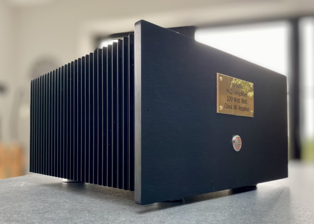
THD distortion in CFA amplifiers, in general, is not as low as that in VFAs for simple implementations. However, the differences between the two are negligible in more advanced designs that utilise EF2 or EF3 output stages and TIS beta helper techniques. For example, the 100W RMS CFA nx2-Amplifier using an EF2 output stage produces less than 30 ppm distortion at 100W output into 8 ohms and less than 40ppm at 200W into 4 ohms. It is quite easy to increase the overall loop gain to get distortion down to the single-digit PPM level by adding extra stages, but this will only bring bragging rights and not sonic benefits. However, where CFAs excel is in low IMD distortion, where in the example quoted, the full power (so 2 x 25W RMS tones) 19+20 kHz IMD figure is better than 90 dB with little other than the 1kHz beat tone observable. At any power levels a little below this, the figure quickly betters 100 dB, and this is a reflection of the excellent open-loop HF linearity and the current on demand behaviour of the front-end diamond buffer stage.
So, if CFAs had come along before VFAs, it is my contention is that there would have been no SID or TIM, no slew rate limiting at HF, compensation would have been easier, and the euphonic sound of a well-designed tube amplifier would have been taken to the next level with lower overall distortion, better bass, and improved top-end performance of a well-designed solid-state amplifier; there would have been none of the compromises that plagued earlier VFA solid-state design efforts, or the decades long search to refine the topology and the ludicrous claims about zero global feedback amplifiers ‘sounding better’ wouldn’t be a thing.
Finally, I want to talk a little about the current state of the art with regard to VFAs because I do not want to leave anyone with the impression that they are ‘no good’. Modern VFAs have addressed the issues I raised here and in the article linked at the beginning of this write-up. You don’t get TIM on modern designs, and the onset of slew rate limiting is generally up near 80kHz or higher, so it is well away from any audio band signal. Further, contemporary designers are a lot more adept at compensating their amplifiers, thanks largely to the use of circuit simulators which do a good job of producing the necessary loop gain and phase plots needed to do the job.
To summarise, this is why I prefer CFAs
- CFAs can never slew rate limit like VFAs
- They cannot produce SID or TIM since the front-end diamond buffer produces current on demand to charge/discharge any loop compensation capacitance around the TIS
- They offer high open-loop linearity as a matter of course and feature low IMD at full power, even with low loop gains
- Fast, symmetrical rise/fall times come as standard with the topology
- They display closed loop gain vs frequency independence in lower loop gain implementations
- Power CFA loop gain bandwidths are typically >5 kHz, with many designs achieving loop gain bandwidths of 20 kHz or better (see the sx-Amplifier, kx2 and nx2 amplifiers, for example); their frequency versus distortion profiles are generally flat over the audio band.
- Variants with open loop gains similar to those of VFAs show the same levels of THD, i.e. single digit ppm if its single digit ppm that floats your boat
- They offer more than adequate PSRR – typically >70dB
- Finally, audio power CFAs are elegantly simple and perform as well as, or better than, the many different VFA variants that were developed to fix that topologies weaknesses.
Further Reading
- Audio Power Amplifier Design Handbook by Douglas Self
- Designing Audio Power Amplifiers by Robert Cordell
- Op Amps for Everyone by Ron Mancini, Steven J. Logan, and Matt Duff (Texas Instruments)
- The Analysis and Design of Linear Circuits by Roland E. Thomas and Albert J. Rosa
- High-Speed Amplifier Techniques: A Designer’s Companion by Barrie Gilbert and Art Kay
- The Monolithic Operational Amplifier: A Tutorial Study by James E. Solomon (ISSCC 1974)
- Transient Intermodulation Distortion in Solid-State Power Amplifiers by Matti Otala (IEEE Transactions on Audio, Electroacoustics and Ultrasonics, 1972)
- Tradeoffs and Optimization in Analog CMOS Design by B. Razavi
- Understanding and Using Current-Feedback Amplifiers by Analog Devices (Application Note)
- Op-Amp Stability and Compensation: Design Techniques and Tips by Analog Devices (Application Note)
- ‘In defense of the current feedback amplifier’ by Sergio Franco, EDN , Aug 23, 2017
- Analog Circuit Design by Sergio Franco, 2015
Leave a Reply